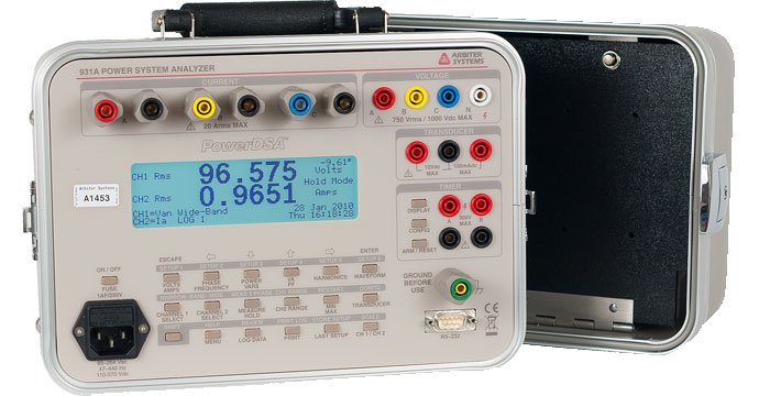
Model 931A Power System Analyzer
Model 931A Power System Analyzer
Full featured Model 931A goes beyond basic and power quantity measurements, supporting two way communications, transducer calibration, timer features and more.
Model 931A, with state-of-the-art PowerDSA™ Digital Signal Analysis, make more measurements, more accurately, and at a lower price than ever before. Basic accuracy of 0.05 % of reading and 0.05 ° phase, harmonic analysis, and full three-phase capability are standard. Model 931A also incorporate full two way serial communication for use in power quality trend monitoring. The model expands usability by including transducer calibration and timer features.
Model 931A, featuring PowerDSA™ Digital Signal Analysis, measures all of the basic quantities: true-rms voltage and current, frequency and phase angle, as well as power quantities such as watts (W), watthours (Wh), volt-amperes (VA), volt-ampere hours (VAh), volt-amperes reactive (VAR), volt-amperes reactive hours (VARh), and power factor (PF), all with 0.11 % basic accuracy.
Measure harmonics and view the results graphically on the high contrast 240x64 graphic display. The two channels are normalized to Channel 1 fundamental phase, so you can see, for example, the relationship between current waveform distortions and voltage phase.
Other key functions include a timer/counter for measuring relay operating times, elapsed test times, or for counting input rates and events. The 931A include a full three-phase input section, for automated three-phase measurement sequences, complete with multiple display modes (see Key Features tab, below)
- Top-of-the-line Power Measurement and Analysis product
- Measures basic and power quantities
- High accuracy
- Field ready
- Multiple display options including three phase displays
Basic three-phase display - Voltage, current, phase, frequency and power quantities on one convenient display.
Vector display - view voltages, currents and phase angles with their vector representation.
Voltage/Current Sequence display - view voltage, current and phase along with positive, negative and zero sequence values.
Energy display - view voltage, current, phase, frequency and energy quantities on one convenient display.
- Power Trend Monitor and recording system - verify phase relation, phase rotation, power direction, load balance and more
- Transducer Calibration supported
- CT/PT Ratios
- Extended Measurement Ranges
Input
Input
| Basic Inputs | Supports two main measurement channels, Channel 1 and Channel 2. Any voltage or current input signal may be selected for either channel. For basic measurements (voltage, current, frequency, phase angle) any combination of inputs may be used. For power and energy measurements (active power, apparent power, reactive power and power factor), one voltage and one current must be selected. For three-phase measurements, the input configuration is selected automatically, based on the measurement type (for example, 3-phase 4-wire 3-element). |
Voltage
| Input Range | 1.5 Vrms to 750 Vrms (underrange to 200 mV) [2 Vdc to 1000 Vdc (Model 931A Only)] |
| Inputs | Four; A, B, C, N |
| Impedance | 1 megohm |
| Leakage | < 3.5 mA per IEC348 and UL1244 |
Current
| Input Range | 0.04 Arms to 20 Arms (underrange to < 1 mA) |
| Inputs | Three; A, B, C, plus synthesized neutral |
| Burden | 0.01 ohm maximum |
| Isolation | Transformer, 1000 Vrms |
| Neutral | Synthesized, -(A+B+C) |
Timer
| Inputs | Two; 4 Vdc to 300 Vdc; 20 Vrms to 300 Vrms; or dry contact/thyristor output |
| Isolation | Optical, 300 Vrms, each channel |
Transducer
| Range | 0 to 1, 0 mAdc to 100 mAdc and 0 Vdc to 10 Vdc |
| Protection | Overvoltage to 120 V, both inputs |
| Isolation | Optical, 300 Vrms |
Measurements
Voltage and Current
| Method | Wideband: True rms, 3 kHz Bandwidth |
| Accuracy | 0.05 % of reading |
| Underrange | < 1 % of reading, typical at 0.3 mArms |
| DC Voltage | 0.1 % of reading + 25 mVdc, typical |
Phase Angle
| Input | Channel 1 to Channel 2 |
| A-B Range | 0 ° to 360 ° or ± 180 ° |
| A-B Accuracy | 0.05 ° |
| Underrange | < 1 °, typical at 0.3 mArms |
Frequency
| Input | Channel 1 |
| Range | 20 Hz to 500 Hz (underrange to 5 Hz) |
| Accuracy | 0.005 % of reading |
Harmonics
| Input | Channel 1 or Channel 2 |
| Range | 2nd to 50th Harmonic (50 Hz or 60 Hz fundamental) |
| Accuracy | 0.01 % THD + 5 % of reading |
| Display | THD; K-factor; Amplitude bar graph; and individual harmonic magnitude and phase (simultaneous) |
Waveform Display
Channel 1 and/or Channel 2
Power
| Range | 0 MVA or MVAh to 99999 MVA or MVAh |
| Accuracy | 0.11 % of VA, for VA, VAR, and W |
Timer
| Range | 0.0001 seconds to 9999.9 seconds, or 0.01 cycles to 999999 cycles |
| Accuracy | 0.005 % of reading + 1 digit |
| AC Trigger | Add 1 ms maximum, 0.15 ms at 120 Vrms |
Transducer Accuracy
0.05 % of reading + 0.01 % range
Interface
Operator
| Display | 240x64 graphic LCD with cold-cathode fluorescent lamp (CCFL) backlight |
| Keypad | 21 function keys plus On/Off |
| Memory | EEPROM (calibration data) |
| Data | Instrument calibration data |
Power Requirements
Internal Battery
| Type | Nickel-Metal Hydride (NiMH) |
| Operation | 8 hours typical |
| Charging Time | 8 hours typical; fast + float charge |
External
| Range | 85 Vac to 264 Vac, 47 Hz to 440 Hz, 15 VA maximum |
| Safety | Designed to meet UL, CSA, VDE |
General
Physical
| Instrument/Size | 205 mm x 305 mm x 225 mm (8 in x 12 in x 8.75 in) |
| Weight | 5.8 kg (12.8 lbs), net |
Environmental
| Temperature | Operating: 0 °C to + 50 °C |
| Humidity | Noncondensing |
| Included | |
|---|---|
| 812 | Safety Ground Lead |
| AS0094000 | Operation Manual (931A) |
| CA0019806 | RS-232 Null Modem Cable, DB9F-DB9F, 2 m (6 ft) length |
| P09R | Power Cord, North America, Right Angle |
| Available | |
| 09311A | 400 A 20:1 Precision CT, 0.1 % Accuracy |
| 811AT-8 | 3-Phase Univ. Test Plug Current Lead Set |
| 813AT-8 | 3-Phase Safety Voltage Lead Set |
| 815AT-8 | Model 815 Fused Safety Voltage Probe Lead Set |
| 816AT-8 | 3-Phase Spade-Lug Current Lead Set |
| 817AA-8 | 1-Phase Clamp-On CT Test Lead |
| 817AT-8 | 3-Phase Clamp-On CT Lead Set |
| 818AT-8 | 3-Phase Safety C-Hook Current Lead Set |
| 819xyz-8 | Modified Safety Clip Lead Set |
| 841A | Series Test Jack Isolator Paddle |
| 842A | Three - Series Test Jack Isolator Paddles with 60 cm Nylon Cord |
| 842B | Four - Series Test Jack Isolator Paddles with 60 cm Nylon Cord |
| AP0001300 | 1000:1 Clamp-on CT, 1000 A (Current Output) |
| AP0012800 | 1000:1 Clamp-on CT, 200 A, 1 mA/A (100 mA @ 100 A ac) |
| AP0012900 | 250:5, 500:5, 1000:5, 1000 A rms, Clamp-on CT |
| AS0035901 | Adjustable Tilt Handle/Bail Assembly |
| AS0036000 | 400 A CT Bracket (each) |
| AS0060000 1 | PowerCSV Application Software for Models 931A and 930A |
| AS0079001 | Universal Test Plug Current Shunt, A Phase Red |
| AS0079002 | Universal Test Plug Current Shunt, B Phase Yellow |
| AS0079003 | Universal Test Plug Current Shunt, C Phase Blue |
| AS0079030 | Universal Test Plug Current Shunt, Set of Three |
| CN0030500 | Adaptor Banana Shielded - Red |
| CN0030501 | Adaptor Banana Shielded - Black |
| P01R-P10R | Country specific power cord with right angle female end |
1 Available via download only
| Click to Download Latest Version of Software | |
|---|---|
| 930/31_PowerCSV_14Oct2010_2002 | For Models 930 and 931 - requires memory option |
| 930/31_PowerCSV_SHA256_14Oct2010_2002 | 930/31_PowerCSV SHA256 checksum |
| Tera Term_01Jan2010_23 | This is a very good HyperTerminal replacement. Able to capture data from Models 930A and 931A. Also able to program the GPS Satellite Controlled Clocks via serial commands. |
| Tera Term SHA256_01Jan2010_23 | Tera Term SHA256 checksum |
Software Version and Related Information
Common Controls Update for PowerCSV
04Oct2002
Current
PowerCSV for Models 930 and 931 (930/31_PowerCSV)
| Version | Rev Level | Version Notes |
|---|---|---|
| 14Oct2010 | 2.002 |
|
| 28Apr2009 | 2.001 |
|
930/31_PowerCSV_SHA256
| Version | Rev Level | Version Notes |
|---|---|---|
| 14Oct2010 | 2.002 |
Terminal Emulation Program (Tera Term)
Free software terminal emulator (communications program) for Microsoft Windows.
- Tera Term (Pro) is a free software terminal emulator (communication program) for MS-Windows.
- Supports VT100 emulation, telnet connection, serial port connection, etc.
- Compatible with Windows 98, Windows NT, Windows 2000, Windows XP, Vista, Windows 7
Tera Term SHA256
| Firmware Information (EPROM based firmware is not available for download) | |
|---|---|
| 929/30/31_Firmware_05Dec2018 | Requires an EPROM update from Arbiter. The same update works for Models 929, 930 and 931. |
Firmware Version and Related Information
EPROM update (929/30/31_Firmware)
| Version | Rev Level | Version Notes |
|---|---|---|
| 05Dec2018 | Updates are not security related.
|
|
| 13Jul2018 | Updates are not security related.
|
|
| 08Dec2010 |
|
|
| 10Feb2010 |
|
App Note 110: Measuring Low-Level Signals w/Model 931A
Download application_note_110.pdf (25 kB) »
App Note 113: Using Clamp-On Current Transfomers (CTs) with Arbiter Power Analyzers
Download application_note_113.pdf (89 kB) »
Logging Files from the Model 931A Power System Analyzer
Download pd0044600_logging_931_930_data_with_teraterm.pdf (142 kB) »
Model 09311A 400 Amp Auxiliary Current Transformer
Download 09311a.pdf (252 kB) »
Model 09311A 400 Amp Auxiliary Current Transformer Español
Download 09311a_ct_espanol.pdf (125 kB) »
Overview Presentation of Model 931A Power System Analyzer
Download 931a_seminar.pdf (732 kB) »
Sealed Nickel-Metal Hydride cells (MSDS)
Download sealed_nickel-metal_hydride.pdf (558 kB) »