Model 1206B/C GNSS Synchronized Clock (40ns)
Model 1206B/C GNSS Synchronized Clock (40ns)
Next generation multi-satellite timing source for precision applications. Featuring rubidium holdover oscillator, enhanced performance and security (EPS).
Model 1205B/C 1206B/C User Manual
Download PDF(4 MB) »
Model 1205B/C and Model 1206B/C Setup Guide
Download PDF(2 MB) »
Model 1206B/C Data Sheet
Download PDF(786 kB) »
GNSS Antenna Data Sheet
Download PDF(4 MB) »
The Model 1206B/C introduces the rubidium holdover oscillator to the GNSS product line. The Model 1206B/C delivers better than 40 ns typical accuracy and includes the most highly sought after features in a precision time clock as standard plus enhanced performance and security (EPS).
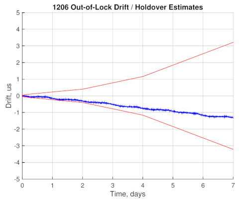
The standard holdover oscillator maintains accuracy of 1 µs/24 h when not tracking satellites. In addition to enhanced performance, Arbiter Systems' new EPS technology includes GNSS anti-spoofing and secure password-protected and encrypted configuration interface providing robust, reliable synchronization.
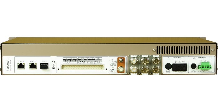
The Model 1206B/C timing signals are available via the three Ethernet ports, the thirty-two pin terminal block and from the three available option slots. The three 10/100 Ethernet ports (copper standard, fiber optional) provide status, configuration as well as network timing supporting the NTP, SNTP, PTP (IEEE 1588Power Profile supported), SNMP, ICMP, TCP, SSH, SSL, HTTP, HTTPS and DHCP protocols. The thirty-two pin terminal block provides access to the Model 1206B/C standard inputs, outputs and legacy communication ports. Two inputs, an event timer and a frequency monitor, are included along with six Programmable Pulse outputs, a modulated IRIG-B output, a FET output, relay contacts, two RS-232 ports and a RS- 422/485 port (transmit only).
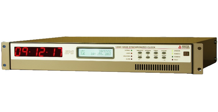
The Model 1206B/C is available with two front panel configurations (see photos and Key Features tab). Each product includes the GNSS antenna and cable, a terminal power strip, and a rack mount kit, all backed by a Five Year Limited Warranty to the original owner/purchaser.
- Rubidium holdover oscillator
- Accuracy of ± 100 ns, ± 40 ns typical
- Standard: NTP/PTP server, unmodulated IRIG-B, modulated IRIG-B, 1 PPS, and One Form C (SPDT) fail-safe locked relay, Power System Time and Frequency Monitor
- Output options include: 50 Ohm programmable pulse, 75 Ohm programmable pulse, 50 Ohm frequency (AC or DC coupled), 75 Ohm frequency (AC or DC coupled), dual relays, and redundant GNSS receiver
- 1206C includes both the operating status LEDs, the LCD display and keypad, and includes a large LED time display.
- IEEE C37.118.1-2011 compliant for Synchrophasor use.
Enhancements
- Enhanced Performance and Security (EPS)
- EPS benefits include multi-system timing sources (GPS/ GLONASS/Galileo/BeiDou), standard holdover oscillator, multiple levels of security, secure communications, and anti-spoofing technology
- Redundant power supply available
- Redundant GNSS receiver available
- Second serial port standard
- IRIG-B compliant with IEEE Std. C37.118.1-2011
Build-a-Part Ordering Structure:
* denotes standard selection
| 1206 | - | x | - | Axx | - | Bxx | - | Cxx | - | Dxx | - | Exx | - | Fxx | - | Gxx | - | Hxx | - | Jxx | |
| Series | |||||||||||||||||||||
| Model | |||||||||||||||||||||
| B = LCD Display | |||||||||||||||||||||
| C = LCD Display & Large Segment LED Time Display | |||||||||||||||||||||
| Power Supply A | |||||||||||||||||||||
| A01* = 100 Vac to 240 Vac, 100 Vdc to 350 Vdc | |||||||||||||||||||||
| A02 = 24 Vdc to 48 Vdc | |||||||||||||||||||||
| Power Supply B | |||||||||||||||||||||
| B00* = Not Installed | |||||||||||||||||||||
| B01 = 100 Vac to 240 Vac, 100 Vdc to 350 Vdc | |||||||||||||||||||||
| B02 = 24 Vdc to 48 Vdc | |||||||||||||||||||||
| Holdover Oscillator | |||||||||||||||||||||
| C01* = 1 µs/24 h | |||||||||||||||||||||
| Network Connectors | |||||||||||||||||||||
| D01 = 3 - 10/100BT | |||||||||||||||||||||
| D02 = 2 - 10/100BT, 1 - Multimode Fiber | |||||||||||||||||||||
| D03 = 1 - 10/100BT, 2 - Multimode Fiber | |||||||||||||||||||||
| D04 = 3 - Multimode Fiber | |||||||||||||||||||||
| I/O Slot A | |||||||||||||||||||||
| E00* = Not Installed | |||||||||||||||||||||
| E01 = Programmable Pulse Outputs, 50 Ohm | |||||||||||||||||||||
| E02 = Programmable Pulse Outputs, 75 Ohm | |||||||||||||||||||||
| E03 = 1.544/2.048 MHz Outputs, 50 Ohm, DC Coupled | |||||||||||||||||||||
| E04 = 1.544/2.048 MHz Outputs, 75 Ohm, DC Coupled | |||||||||||||||||||||
| E05 = 1.544/2.048 MHz Outputs, 50 Ohm, AC Coupled | |||||||||||||||||||||
| E06 = 1.544/2.048 MHz Outputs, 75 Ohm, AC Coupled | |||||||||||||||||||||
| E07 = Modulated IRIG-B Outputs | |||||||||||||||||||||
| E08 = Programmable Pulse Fiber-Optic Outputs | |||||||||||||||||||||
| E09 = Programmable Pulse 24 Vdc Outputs | |||||||||||||||||||||
| E10 = Dual Relay Outputs | |||||||||||||||||||||
| E11 = System 1 PPS Outputs, 50 Ohm | |||||||||||||||||||||
| E12 = System 1 PPS Outputs, 75 Ohm | |||||||||||||||||||||
| E13 = Redundant GNSS Receiver | |||||||||||||||||||||
| E14 = Frequency Outputs, 50 Ohm, DC Coupled | |||||||||||||||||||||
| E15 = Frequency Outputs, 75 Ohm, DC Coupled | |||||||||||||||||||||
| E16 = Frequency Outputs, 50 Ohm, AC Coupled | |||||||||||||||||||||
| E17 = Frequency Outputs, 75 Ohm, AC Coupled | |||||||||||||||||||||
| E18 = 1 MHz Sine Wave Outputs, 50 Ohm | |||||||||||||||||||||
| E19 = 5 MHz Sine Wave Outputs, 50 Ohm | |||||||||||||||||||||
| E20 = 10 MHz Sine Wave Outputs, 50 Ohm | |||||||||||||||||||||
| I/O Slot B | |||||||||||||||||||||
| F00* = Not Installed | |||||||||||||||||||||
| F01 = Programmable Pulse Outputs, 50 Ohm | |||||||||||||||||||||
| F02 = Programmable Pulse Outputs, 75 Ohm | |||||||||||||||||||||
| F03 = 1.544/2.048 MHz Outputs, 50 Ohm, DC Coupled | |||||||||||||||||||||
| F04 = 1.544/2.048 MHz Outputs, 75 Ohm, DC Coupled | |||||||||||||||||||||
| F05 = 1.544/2.048 MHz Outputs, 50 Ohm, AC Coupled | |||||||||||||||||||||
| F06 = 1.544/2.048 MHz Outputs, 75 Ohm, AC Coupled | |||||||||||||||||||||
| F07 = Modulated IRIG-B Outputs | |||||||||||||||||||||
| F08 = Programmable Pulse Fiber-Optic Outputs | |||||||||||||||||||||
| F09 = Programmable Pulse 24 Vdc Outputs | |||||||||||||||||||||
| F10 = Dual Relay Outputs | |||||||||||||||||||||
| F11 = System 1 PPS Outputs, 50 Ohm | |||||||||||||||||||||
| F12 = System 1 PPS Outputs, 75 Ohm | |||||||||||||||||||||
| F14 = Frequency Outputs, 50 Ohm, DC Coupled | |||||||||||||||||||||
| F15 = Frequency Outputs, 75 Ohm, DC Coupled | |||||||||||||||||||||
| F16 = Frequency Outputs, 50 Ohm, AC Coupled | |||||||||||||||||||||
| F17 = Frequency Outputs, 75 Ohm, AC Coupled | |||||||||||||||||||||
| F18 = 1 MHz Sine Wave Outputs, 50 Ohm | |||||||||||||||||||||
| F19 = 5 MHz Sine Wave Outputs, 50 Ohm | |||||||||||||||||||||
| F20 = 10 MHz Sine Wave Outputs, 50 Ohm | |||||||||||||||||||||
| I/O Slot C | |||||||||||||||||||||
| G00* = Not Installed | |||||||||||||||||||||
| G01 = Programmable Pulse Outputs, 50 Ohm | |||||||||||||||||||||
| G02 = Programmable Pulse Outputs, 75 Ohm | |||||||||||||||||||||
| G03 = 1.544/2.048 MHz Outputs, 50 Ohm, DC Coupled | |||||||||||||||||||||
| G04 = 1.544/2.048 MHz Outputs, 75 Ohm, DC Coupled | |||||||||||||||||||||
| G05 = 1.544/2.048 MHz Outputs, 50 Ohm, AC Coupled | |||||||||||||||||||||
| G06 = 1.544/2.048 MHz Outputs, 75 Ohm, AC Coupled | |||||||||||||||||||||
| G07 = Modulated IRIG-B Outputs | |||||||||||||||||||||
| G08 = Programmable Pulse Fiber-Optic Outputs | |||||||||||||||||||||
| G09 = Programmable Pulse 24 Vdc Outputs | |||||||||||||||||||||
| G10 = Dual Relay Outputs | |||||||||||||||||||||
| G11 = System 1 PPS Outputs, 50 Ohm | |||||||||||||||||||||
| G12 = System 1 PPS Outputs, 75 Ohm | |||||||||||||||||||||
| G14 = Frequency Outputs, 50 Ohm, DC Coupled | |||||||||||||||||||||
| G15 = Frequency Outputs, 75 Ohm, DC Coupled | |||||||||||||||||||||
| G16 = Frequency Outputs, 50 Ohm, AC Coupled | |||||||||||||||||||||
| G17 = Frequency Outputs, 75 Ohm, AC Coupled | |||||||||||||||||||||
| G18 = 1 MHz Sine Wave Outputs, 50 Ohm | |||||||||||||||||||||
| G19 = 5 MHz Sine Wave Outputs, 50 Ohm | |||||||||||||||||||||
| G20 = 10 MHz Sine Wave Outputs, 50 Ohm | |||||||||||||||||||||
| Rear Panel Connector | |||||||||||||||||||||
| H00* = Not Installed | |||||||||||||||||||||
| H01 = Screw Terminations | |||||||||||||||||||||
| H02 = Crimp Terminations | |||||||||||||||||||||
| Relay | |||||||||||||||||||||
| J01* = Standard Voltage (30 Vdc/250 Vac) | |||||||||||||||||||||
| J02 = High DC-Voltage (300 Vdc/250 Vac) | |||||||||||||||||||||
Receiver Characteristics
Timing Accuracy
| Accuracy Note | Specifications apply at the 1 PPS/IRIG_B unmodulated/PP/PTP outputs when receiving one satellite in Position Hold Mode, as of date of publication. |
| Accuracy UTC/USNO | ± 100 ns peak |
| Typical | ± 40 ns peak |
Position Accuracy
2 meters, rms
Satellite Tracking
Seventy-two (72) channel receiver: GPS L1C/A, GLONASS L1OF, Galileo E1B/C, and BeiDou B1I
Acquisition
- 55 seconds typical, cold start
- 25 seconds, typical, warm start
- 3 seconds, typical, hot start
Oscillator
| Type | Rubidium |
| Stability | 1 µs/24 h
|
| Patent(s) | High-Reliability Holdover Method and Topologies: No. US 9,326,926 & US 9,979,406 B2 |
I/O Configuration
Output Connectors
One 32 pin pluggable terminal strip connector:
Output Signals
- Programmable Pulse (six outputs)
- IRIG-B modulated
- MOSFET
- Analog Input
- Event Input
- Relay Contacts
- RS-232 (2 ports)
- RS-485 (transmit only)
IRIG-B Modulated
One IRIG-B modulated output, 4 Vpp, 20 ohms source impedance. Configurable to Local or UTC time with C37.118.1 on or off, settings independent from Programmable Pulse IRIG-B output.
MOSFET
300 volt, 1 watt power dissipation open-drain FET driver with 24 Vdc output.
Programmable Pulse Output
Six programmable pulse outputs, high-drive 5 Vdc (125 mA at > 4 Vdc)
- IRIG-B unmodulated (UTC/Local, C37.118.1 On/Off. Settings are independent from main IRIG-B signal.)
- Every 1 second to 60,000 seconds, starts top of the second
- Hourly at a specified offset
- Daily at a specified time of day
- One shot at a specified time of year
- Slow Code (UTC/LCL)
- DCF-77
Pulse polarity and pulse duration are programmable, duration from 0.01 seconds to 600 seconds, except in one-shot mode, where the output is Low prior to the specified time and High thereafter.
Relay Contacts
One Form C (SPDT) fail-safe, 8 A at 250 Vac; configurable to Out-of-Lock, Fault, Alarm, Stabilized, or Programmable Pulse
Input Signals
Analog Input
One single phase AC line voltage (50 Hz / 60 Hz, 300 Vac) input provides accurate measurements of system frequency, frequency error, and time deviation.
Event Inputs
One event timer channel with 100 ns resolution is standard. This function is driven by an external 5 V CMOS/TTL signal.
Interface
Operator
| Display |
|
| Functions |
|
| Status LEDs |
|
| Keyboard | Eight keys; select display functions |
| USB | Micro-USB |
| Setup | Web based configuration |
System
| Ethernet | 3 - Ethernet ports: 10/100 BT (standard) or Fiber (optional) Protocols: NTP, SNTP, PTP (Power Profile), SNMP, ICMP, TCP, SSH, SCP, SSL, HTTP, HTTPS, DHCP |
| RS-232 | 2 - RS-232 ports (TXD, RXD, GND) 1200 baud to 230,400 baud; 7 or 8 data bits; 1 or 2 stop bits; even/odd/no parity |
| RS-422/485 | 1 - RS-422/485 port (TXD+,TXD-) |
| Broadcast modes |
|
| Connector | RS-232 and RS-422/485 are part of the 32 pin terminal block. |
Power Requirements
Accommodates any combination of the two available power supplies in a single or redundant configuration. Choices include an universal supply or a low dc supply, both with surge withstand capability.
Standard
| Voltage | Universal Low DC |
| Inlet | Secure Pluggable Terminal Strip |
General
Physical
| Size | 425 mm x 280 mm x 44 mm (16.75 in x 11 in x 1.75 in) |
| Weight | 2 kg (4.5 lbs), net |
| Ground Block | Antenna protective ground. Copper, with M5 (10-32) stud and nut. Connects internally to gas discharge tube (GDT) lightning surge suppressor. |
| Antenna | Cable Connection: F-type |
| Antenna Cable | Type: RG-6, 15 m (50 ft) provided |
| Antenna Mounting | 0.75 in pipe (1 in - 14 marine) thread |
Environmental
| Temperature | Operating: - 20 °C to + 40 °C |
| Humidity | Noncondensing |
| EMC | Conducted emissions: power supply complies with FCC 20780, Class A and VDE 0871/6.78 Class A Surge withstand capability (SWC), power inlet: designed to meet ANSI/IEEE C37.90-1 and IEC 61000-4 |
Certificates and Approvals
CE mark/label and certificate
One option can be selected from each of the letter categories (A, B, C, D, E, F, G, H, J) listed below; except Power Supply which accommodates two.
A power supply and holdover oscillator must be specified.
| I/O | |
|---|---|
| 1206optE01/F01/G01 | Programmable Pulse Outputs, 50 Ohm, Dual BNC (Slot A/B/C) |
| 1206optE02/F02/G02 | Programmable Pulse Outputs, 75 Ohm, Dual BNC (Slot A/B/C) |
| 1206optE03/F03/G03 | 1.544/2.048 MHz Outputs, 50 Ohm, DC Coupled, Dual BNC (Slot A/B/C) |
| 1206optE04/F04/G04 | 1.544/2.048 MHz Outputs, 75 Ohm, DC Coupled, Dual BNC (Slot A/B/C) |
| 1206optE05/F05/G05 | 1.544/2.048 MHz Outputs, 50 Ohm, AC Coupled, Dual BNC (Slot A/B/C) |
| 1206optE06/F06/G06 | 1.544/2.048 MHz Outputs, 75 Ohm, AC Coupled, Dual BNC (Slot A/B/C) |
| 1206optE07/F07/G07 | Modulated IRIG-B Outputs, Dual BNC (Slot A/B/C) |
| 1206optE08/F08/G08 | Programmable Pulse, Fiber-Optic Outputs, Dual ST (Slot A/B/C) |
| 1206optE10/F10/G10 | Dual Relay Outputs, Dual Terminal Strip (Slot A/B/C) |
| 1206optE11/F11/G11 | System 1 PPS Outputs, 50 Ohm, Dual BNC (Slot A/B/C) |
| 1206optE12/F12/G12 | System 1 PPS Outputs, 75 Ohm, Dual BNC (Slot A/B/C) |
| 1206optE13 | Redundant GNSS Receiver (Slot A) |
| 1206optE14/F14/G14 | Frequency Outputs, TTL, 50 Ohm DC Coupled, Dual BNC (Slot A/B/C) |
| 1206optE15/F15/G15 | Frequency Outputs, TTL, 75 Ohm DC Coupled, Dual BNC (Slot A/B/C) |
| 1206optE16/F16/G16 | Frequency Outputs, TTL, 50 Ohm AC Coupled, Dual BNC (Slot A/B/C) |
| 1206optE17/F17/G17 | Frequency Outputs, TTL, 75 Ohm AC Coupled, Dual BNC (Slot A/B/C) |
| 1206optE18/F18/G18 | 1 MHz Sine Wave Outputs, 50 Ohm, Dual BNC (Slot A/B/C) |
| 1206optE19/F19/G19 | 5 MHz Sine Wave Outputs, 50 Ohm, Dual BNC (Slot A/B/C) |
| 1206optE20/F20/G20 | 10 MHz Sine Wave Outputs, 50 Ohm, Dual BNC (Slot A/B/C) |
| 1206optH01 | Screw Terminal Connector (1205/1206) |
| 1206optH02 | Crimp Terminal Connector (1205/1206) |
| 1206optJ01 | Standard Voltage Relay (30 Vdc/250 Vac) |
| 1206optJ02 | High DC-Voltage Relay (300 Vdc/250 Vac) |
| Power | |
| 1206optA01 | 100 Vac to 240 Vac, 100 Vdc to 350 Vdc Secure Pluggable Terminal Strip and Surge Withstand |
| 1206optA02 | 24 Vdc/48 Vdc Secure Pluggable Terminal Strip and Surge Withstand |
| 1206optB01 | 100 Vac to 240 Vac, 100 Vdc to 350 Vdc Secure Pluggable Terminal Strip and Surge Withstand |
| 1206optB02 | 24 Vdc/48 Vdc Secure Pluggable Terminal Strip and Surge Withstand |
| Oscillator | |
| 1206optC01 | Holdover Rubidium 1 µs/24 h |
| Included | |
|---|---|
| AS0099200 | Arbiter Universal GNSS Antenna |
| AS0105200 | Rack Mount Kit (12xx series 1.5 RU) (preinstalled) |
| CA0021315 1 | 15 m (50 ft) RG-6 Antenna Cable, RoHS |
| Available | |
| AP0003400 2 | BNC (Male) Breakout to 100 mm Wires |
| AP0008900 3 | BNC (Female) Breakout to 100 mm Wires |
| AP0013400 | GNSS Antenna Cable Splitter, F-Type, 950-2150 MHz, One Port Pass DC |
| AP0014900 4 | BNC (Female) Breakout to Screw Terminal |
| AP0015000 5 | BNC (Male) Breakout to Screw Terminal |
| AS0044600 | Antenna Mounting Kit |
| AS0044700 6 | 21 dB In-Line Pre-amplifier |
| AS0048900 | Antenna Grounding Block Kit, RoHS |
| AS0094500 | GNSS Surge Arrester |
| AS0102700 | Screw Terminal Connector H01 (1205/1206) |
| CA0021330 1 | 30 m (100 ft) RG-6 Antenna Cable, RoHS |
| CA0021338 1 | 38 m (125 ft) RG-6 Antenna Cable, RoHS |
| CA0021345 1 | 45 m (150 ft) RG-6 Antenna Cable, RoHS |
| CA0021350 1 | 50 m (164 ft) RG-6 Antenna Cable, RoHS |
| CA0021360 1 | 60 m (200 ft) RG-6 Antenna Cable, RoHS |
| CA0021375 1 | 75 m (250 ft) RG-6 Antenna Cable, RoHS |
| CA0034201 | Power Cord, 250V, Cont. Europe, w/Conn. |
| CA0034202 | Power Cord, 240V, Australia; NZ; PRC, w/Conn. |
| CA0034203 | Power Cord, 250V, U.K., w/Conn. |
| CA0034209 | Power Cord, 120V, N. Amer, w/Conn. |
| CA0035000 | Power Cable Term Block to IEC320 C14 |
| CN0050700 | Type F, Male, RG-6 Antenna Cable Compression Connector, RoHS |
| CN0050800 7 | Type F, Male, RG-6 Plenum Rated Antenna Cable Compression Connector, RoHS |
| CN0051300 | Type F, Male, RG-11 Antenna Cable Compression Connector, RoHS |
| TF0013200 | Antenna Cable Stripping Tool, RG-6 |
| TF0013300 | Antenna Cable Stripping Tool, RG-11 |
| TF0024000 | Type F, RG-6 Antenna Cable Compression Tool |
| TF0024100 | Type F, RG-11 Antenna Cable Compression Tool |
| WC0004900 1 | 300 m (1000 ft) Roll RG-11 Cable, RoHS |
| WC0005000 1 | 300 m (1000 ft) Roll RG-6 Cable, RoHS |
| WC0005200 8 | 300 m (1000 ft) Roll RG-6 Plenum Rated Cable, RoHS |
1 Stocked length. Custom lengths available from 0.3 m (1 ft) to 300 m (1000 ft). Contact factory.
2 Converts female BNC-terminated coaxial cable to pair of wires.
3 Converts male BNC-terminated coaxial cable to pair of wires.
4 Converts pair of wires to female BNC.
5 Converts pair of wires to male BNC.
6 Used for cable lengths greater than: RG-6 75 m (250 ft) ; RG-11 100 m (328 ft). For the Models 120x: Used for RG-6 cable lengths greater than 100 m (328 ft)
7 Indoor use only. Not weather resistant. Not UV radiation protected.
8 Stocked length. Custom lengths available from 0.3 m (1 ft) to 300 m (1000 ft). Contact factory. Indoor use only. Not weather resistant. Not UV radiation protected.
No additional software information is available for this product
| Firmware Information (EPROM based firmware is not available for download) | |
|---|---|
| 1205_1206_Firmware_01.34_16May2023 | Downloadable. Requires the web interface. |
| 1205_1206_Firmware_SHA256_01.34_16May2023 | 1205_1206_Firmware SHA256 checksum |
| Arbiter All MIB file_03DEC2012_00003 | For use with SNMP clients. |
| Arbiter All MIB File_SHA256_03Dec2012_00003 | Arbiter All MIB File SHA256 checksum |
Firmware Version and Related Information
Downloadable Firmware (1205_1206_Firmware)
Firmware update steps:
- Download the firmware file.
- Unzip the firmware file.
- ***DISCONNECT*** the antenna from the rear panel. The update may still happen but disconnecting the antenna helps smooth the update process.
- Revert to http if using the https interface.
- Upload the tps_os-xx.xx.apf file.
- Reboot the clock after updating firmware to make sure that the new code is loaded.
| Version | Rev Level | Version Notes |
|---|---|---|
| 01.34 | 16May2023 | NOTE: This is a repost. The file posted on 25 May 2023 wrongly included the AIDoIP-01.01.apf file. If you uploaded AIDoIP-01.01.apf after uploading tps3_os-01.34.apf to the clock then you will need to upload tps3_os-01.34.apf again to get all the updates. Updates are not security related.
Reposted to website: 31 May 2023 |
| 01.33 | 07Sep2022 | Updates are not security related.
Reposted to web site: 27 Oct 2022 |
| 01.32 | 22Apr2021 | Updates are not security related.
Posted to web site: 28 Apr 2021 |
| 01.32 | 21Sep2020 | Updates are not security related.
Posted to web site: 13 Oct 2020 |
| 01.31 | 09Sep2020 | Updates are not security related.
Posted to web site: 18 Sep 2020 |
| 01.29 | 12Mar2020 | Updates are not security related.
Posted to web site: 26 May 2020 |
| 01.28 | 10Jan2020 | Updates are not security related.
Posted to web site: 25 February 2020 |
| 01.27 | 24Oct2019 | Updates are not security related.
Posted to web site: 9 November 2019 |
| 01.26 | 12Feb2019 | Updates are not security related.
Posted to web site: 24 May 2019 |
| 01.19 | 23Aug2018 | Updates are not security related.
Posted to web site: 1 October 2018 |
1205_1206_Firmware_SHA256
| Version | Rev Level | Version Notes |
|---|---|---|
| 01.34 | 16May2023 | |
| 01.33 | 07Sep2022 | |
| 01.32 | 22Apr2021 | |
| 01.32 | 21Sep2020 | |
| 01.31 | 09Sep2020 | |
| 01.29 | 12Mar2020 | |
| 01.28 | 10Jan2020 |
Downloadable MIB File (Arbiter All MIB file)
| Version | Rev Level | Version Notes |
|---|---|---|
| 03DEC2012 | 0.0003 |
Downloadable All MIB File checksum (Arbiter All MIB File_SHA256)
| Version | Rev Level | Version Notes |
|---|---|---|
| 03Dec2012 | 0.0003 |
GPS Substation Clock Requirements
Download gps_substation_clock_requirements.pdf (25 kB) »
IRIG-B Time Code Accuracy, IED and System Design Issues
Download irig_accuracy_and_connection_requirements.pdf (31 kB) »
NERC PRC-002 and PRC-018 Compliance Statement
Download pd0042900a_NERC_PRC-002_PRC-018_compliance_statement.pdf (70 kB) »
Time in the Power Industry: How and Why We Use It
Download TimeInThePowerIndustry.pdf (407 kB) »
Why GPS Clocks Are Not Free
Download why_gps_clocks_arent_free.pdf (12 kB) »
Specifying Holdover Performance
Download PD0057900_Specifying_Holdover_Performance.pdf (1 MB) »
App Note 101: Distributing Timing Signals in a High-EMI Environment
Download application_note_101.pdf (90 kB) »
App Note 103: Large Format Displays with Arbiter products
Download application_note_103.pdf (16 kB) »
GPS Antenna Mounting Bracket
Download antenna_mnt_bracket_brief.pdf (462 kB) »
GPS Antenna Mounting Bracket Instructions
Download pd0024700_gps_antenna_mounting_bracket.pdf (580 kB) »
GNSS Antenna Preamplifier Installation Instructions
Download pd0025300_gnss_antenna_preamplifier.pdf (3 MB) »
IRIG Standard 200-16
Download irig-b_200-16.pdf (857 kB) »
IRIG-B Specifications
Download irig_b_spec_brief.pdf (488 kB) »
Windows® Time Service Configuration
Download w32time.pdf (14 kB) »
Chassis Dimensions
Download chassis.pdf (4 MB) »
GNSS Surge Protector Installation Instructions
Download pd0045800_surge_protector_installation_instructions.pdf (110 kB) »
Reducing Overshoot and Ripple in Arbiter Products with High Drive Outputs
Download pd0046200_reducing_high_drive_overshoot.pdf (277 kB) »
Timing Signals, IRIG-B and Pulses
Download pd0043200_timing_signals_overview.pdf (197 kB) »
Antenna Cable Assemblies RoHS2 Declaration of Conformity
Download Antenna_Cable_Assemblies_RoHS2_DoC.pdf (286 kB) »