Model 120A GNSS Synchronized Clock (100ns)
Model 120A GNSS Synchronized Clock (100ns)
Next generation multi-satellite timing source for precision applications that require a compact package.
Model 120A User Manual
Download PDF(676 kB) »
Model 120A User Manual Español
Download PDF(701 kB) »
Model 120A Setup Guide
Download PDF(346 kB) »
Model 120A Setup Guide Español
Download PDF(228 kB) »
Model 120A Data Sheet
Download PDF(626 kB) »
Model 120A Data Sheet Español
Download PDF(556 kB) »
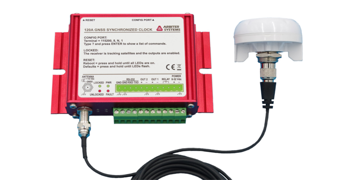
The Model 120A GNSS Synchronized Clock is a multi-satellite system (GPS, Galileo, GLONASS, BeiDou) timing source. Designed as an economical solution for reclosers and other enclosed installations, includes a rugged, low-profile, bulkhead-mount antenna with 5 meters of cable.
The Model 120A has a seventy-two channel receiver, capable of tracking up to 3 satellite constellation systems simultaneously providing a 100 ns rms accuracy.
Two pluggable terminal strip outputs provide IRIG-B unmodulated, 1 PPS, or Programmable Pulse; software selectable. These outputs are configurable to a 50 ohm driver or a high capacity driver. The Model 120A comes standard with two communication ports, one RS-232 and one USB. A SPST relay is also included and is configurable to Out of Lock, Fault, Alarm, Stabilized, or Programmable Pulse.
Low-voltage dc power input accepts + 8 Vdc to + 32 Vdc.
Five year limited warranty from date of delivery.
- Accuracy of ± 100 ns rms
- Two outputs, software selectable signals:
- Unmodulated IRIG-B
- 1 PPS
- Two outputs, software selectable drive capability:
- 50 ohm
- High-drive (125 mA)
- One Form A (SPST) fail-safe relay: 0.12 A at 400 Vdc (400 mW)
- Low dc power input: + 8 Vdc to + 32 Vdc
Enhancements
- Multi-system timing sources (GPS/ GLONASS/Galileo/BeiDou).
- Micro-USB management port.
- Configured through command-line interface.
- Xmodem Firmware updates.
- Wide operating temperature range.
- IRIG-B compliant with IEEE Std. C37.118.1-2011 Synchrophasor use.
Receiver Characteristics
Timing Accuracy
| Accuracy Note | Specifications apply at the output when receiving satellite signals, as of date of publication. |
| Accuracy UTC/USNO | ± 100 ns rms |
Position Accuracy
2 meters, rms
Satellite Tracking
Seventy-two (72) channel receiver: GPS L1C/A, GLONASS L1OF, Galileo E1B/C, and BeiDou B1I
Acquisition
- 50 seconds typical, cold start
- 25 seconds, typical, hot start
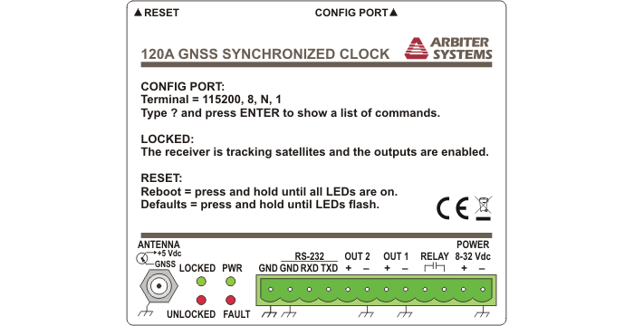
I/O Configuration
Output Connectors
One 12-position pluggable terminal strip:
- Out 1: IRIG-B unmodulated, 1 PPS or Programmable Pulse; software configurable
- Out 2: IRIG-B unmodulated, 1 PPS or Programmable Pulse; software configurable
- RS-232: Transmit, Receive, and Ground
- Relay: SPST fail-safe, 0.12 A at 400 Vdc (400 mW); software configurable
- Power
USB micro connector
USB 2.0 serial port emulation, supports terminal configuration and firmware updates
F-Connector
Antenna, 5 Vdc compatible
Programmable Pulse Output
Two programmable output pulses (Out 1 and Out 2) with software selectable drive capability.
- 50 ohm
- High-drive (125 mA)
Five signal modes:
- IRIG-B unmodulated (UTC/Local, C37.118.1 On/Off.)
- Every 1 second to 999 seconds
- Hourly at a specified offset
- Daily at a specified time of day
- DCF-77
Relay Contacts
One Form A (SPST) fail-safe, 0.12 A at 400 Vdc (400 mW); configurable to Out-of-Lock, Fault, or Programmable Pulse
Interface
Operator
| Status LEDs |
|
System
| USB | Management and configuration. Terminal emulation: 115,200 baud; 8 data bits; 1 stop bit; no parity |
| RS-232 | 1200 baud to 115,200 baud; 7 or 8 data bits; 1 or 2 stop bits; even/odd/no parity Pluggable terminal strip (TxD, RxD, GND) Configuration and Broadcast modes |
| Broadcast modes |
|
| Connector | Pluggable terminal strip |
Power Requirements
Standard
| Voltage | + 8 Vdc to + 32 Vdc, 5 W maximum |
| Inlet | Pluggable terminal strip |
General
Physical
| Size | 110 mm x 85 mm x 30 mm (4.3 in x 3.4 in x 1.2 in), |
| Weight | 0.45 kg (1 lbs), net |
| Antenna | Cable Connection: TNC |
| Antenna Cable | RG-174/U, 5 m (16 ft) provided |
| Antenna Mounting | Bulkhead (0.8 in threaded nut) |
Environmental
| Temperature | Operating: - 40 °C to + 85 °C |
| Humidity | Noncondensing |
Certificates and Approvals
CE mark/label and certificate
| Included | |
|---|---|
| AS0111600 | GPS Antenna with 5 m (16 ft) Cable |
| PD0058300 | Setup Guide (120A) |
| Available | |
| AP0003400 1 | BNC (Male) Breakout to 100 mm Wires |
| AP0008900 2 | BNC (Female) Breakout to 100 mm Wires |
| AP0014900 3 | BNC (Female) Breakout to Screw Terminal |
| AP0015000 4 | BNC (Male) Breakout to Screw Terminal |
| AS0094500 5 | GNSS Surge Arrester |
| AS0099200 6 | Arbiter Universal GNSS Antenna |
| CA0021306 7 | 6 m (20 ft) RG-6 Antenna Cable, RoHS |
| CA0021315 8 | 15 m (50 ft) RG-6 Antenna Cable, RoHS |
| CA0021330 8 | 30 m (100 ft) RG-6 Antenna Cable, RoHS |
| CA0021375 8 | 75 m (250 ft) RG-6 Antenna Cable, RoHS |
| CA0033700 | Micro USB Cable, 6 ft |
| CN0032100 | Adapter Female Type-F to Male TNC |
1 Converts female BNC-terminated coaxial cable to pair of wires.
2 Converts male BNC-terminated coaxial cable to pair of wires.
3 Converts pair of wires to female BNC.
4 Converts pair of wires to male BNC.
5 Use with the AS0099200 GNSS antenna.
6 Available to use when the AS0111600 antenna will not be mounted on the cabinet and for longer cable runs.
7 Use with the AS0099200 GNSS antenna and the Surge Arrester. Custom lengths available from 0.3 m (1 ft) to 300 m (1000 ft). Contact factory.
8 Use with the AS0099200 GNSS antenna. Custom lengths available from 0.3 m (1 ft) to 300 m (1000 ft). Contact factory.
Related Software Information
The Model 120A has an internal user interface. Use any terminal program with Xmodem capability for full function.
| Firmware Information (EPROM based firmware is not available for download) | |
|---|---|
| 120A_Firmware_02Mar2023_0105 | Downloadable. Use the embedded user interface to import file into unit. |
| 120A_Firmware_SHA256_02Mar2023_0105 | 120A_Firmware SHA256 checksum |
Firmware Version and Related Information
Downloadable Firmware (120A_Firmware)
| Version | Rev Level | Version Notes |
|---|---|---|
| 02Mar2023 | 01.05 | Updates are not security related.
Posted to web site: 03 March 2023 |
| 12May2021 | 01.04 | Updates are not security related.
Posted to web site: 02 June 2021 |
| 09Sep2020 | 01.03 | Updates are not security related.
Posted to web site: 09 September 2020 |
| 22Jul2020 | 01.02 | NOTE: This version has a known position data bug that is fixed in version 1.03. Updates are not security related.
Posted to web site: 22 July 2020 |
| 27April2020 | 01.01 | Updates are not security related.
Posted to web site: 29 April 2020 |
120A_Firmware_SHA256
| Version | Rev Level | Version Notes |
|---|---|---|
| 02Mar2023 | 01.05 | Updated to correspond with new firmware release: m120_fw_v0105.bin |
| 12May2021 | 01.04 | Updated to correspond with new firmware release: m120_fw_v0104.bin |
| 09Sep2020 | 01.03 | Updated to correspond with new firmware release: m120_fw_v0103.bin |
| 22Jul2020 | 01.02 | Updated to correspond with new firmware release: m120_fw_v0102.bin |
| 27April2020 | 01.01 | Updated to correspond with new firmware release: m120_fw_v0101.bin |
GPS Substation Clock Requirements
Download gps_substation_clock_requirements.pdf (25 kB) »
IRIG-B Time Code Accuracy, IED and System Design Issues
Download irig_accuracy_and_connection_requirements.pdf (31 kB) »
Time in the Power Industry: How and Why We Use It
Download TimeInThePowerIndustry.pdf (407 kB) »
Specifying Holdover Performance
Download PD0057900_Specifying_Holdover_Performance.pdf (1 MB) »
Model 120A CE Declaration
Download 120A_CE_declaration.pdf (101 kB) »
Antenna Cable Assemblies RoHS2 Declaration of Conformity
Download Antenna_Cable_Assemblies_RoHS2_DoC.pdf (286 kB) »