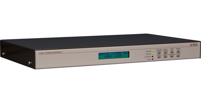
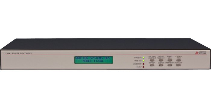
Model 1133A Power Sentinel™
Model 1133A Power Sentinel™
A leader in synchrophasor measurement and analysis, Model 1133A Power Sentinel™ merges precision time synchronization and power measurement features into a single PMU compatible device.
Model 1133A User Manual
Download PDF(4 MB) »
Model 1133A Quick Setup Guide
Download PDF(510 kB) »
Model 1133A Power Sentinel™ Data Sheet
Download PDF(190 kB) »
Model 1133A Power Sentinel™ Data Sheet Español
Download PDF(802 kB) »
Bridging the gap between Precision Timing and Power Quality Measurement, Model 1133A Power Sentinel™ delivers practically unlimited functionality to the electric power professional. Compliant with IEEE C37.118, Model 1133A is a rack mountable Phasor Measurement Unit (PMU) compatible device featuring the highest accuracy possible.
Functionally, the unit provides exceptional support for synchronized timing applications enabling Model 1133A to take a leadership role in synchrophasor measurement and analysis. Measure system phase angle, monitor power quality, derive frequency and time deviations and tackle revenue metering challenges from a single unit. The advanced technology, featuring Arbiter's proprietary EnergyDSA™ Digital Signal Analysis technology makes all of this - and more - possible.
- IEEE C37.118-2005 compatible PMU device
- Synchronized via internal GPS Satellite receiver
- Market leading synchrophasor support
- Revenue Accuracy: 0.025 %
- Power Quality: Harmonics, Flicker, Interruptions
- Phasor Measurements for Stability & Flow Analysis
- System Time & Frequency Deviation
- Internal Data/Event Logging
- Two Year Warranty to the original owner/purchaser
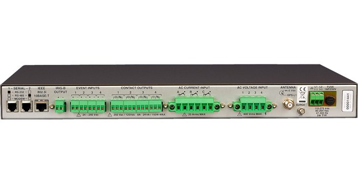
Input/Output
Configuration
| 3 Ø: | 3-element, 2½-element, 2-element, selectable |
| 1 Ø: | 2-element, 1½-element, and 1-element, selectable |
Voltage
| Range (3 Ø/1 Ø) | 0 Vrms to 69 Vrms, 120 Vrms, 240 Vrms, or 480 Vrms, selectable (phase-to-phase for 2 element; phase-to-neutral for 2½ element and 3 element) |
| Overrange | 88 Vrms, 175 Vrms, 350 Vrms, or 700 Vrms, nominal |
Current
| Range (3 Ø/1 Ø) | 2.5 Arms, 5 Arms, 10 Arms, or 20 Arms, selectable, per element |
| Overrange | 2.9 Arms, 5.9 Arms, 11.7 Arms, or 23.5 Arms, nominal (maximum continuous input current: 20 Arms per element) |
VA, W, VAR
| Range | Product of rated voltage and current ranges and number of elements (2½ (3 Ø) and 1½ (1 Ø) element, use 3 and 1, respectively) |
Compensation
| CT and PT | Both magnitude and phase compensation, CT with 12 point nonlinear interpolation |
| Transformer | Both iron and copper compensation |
Frequency
| Range | 45 Hz to 65 Hz, for specified accuracy |
| Harmonics | To 3 kHz |
Inputs
| Insulation | 400 volts, nominal, to neutral/chassis, surge voltage class III Contact Technical Support for more detailed information |
| Connections | Removable screw-clamp terminal block, accepting 0.2 mm to 4 mm2 (#24 to #10 AWG) solid or stranded conductors |
Power Quality
Harmonics Measurement
| Standard | Per IEC 61000-4-7, 100 ms overlapping data window |
| Measurements | THD, K-factor, rms harmonic current and voltage, rms harmonic current and voltage with K-factor compensation (each harmonic magnitude is multiplied by the square of the harmonic number before summing), individual magnitude and phase |
| Logged Data | Selectable, may be regularly logged or registered; or event-logged when user-specified limits are exceeded |
Interruptions Logged Data
Selectable, may be regularly logged or registered; or event-logged when user-specified limits are exceeded
Flicker
| Standard | Per IEC 61000-4-15, Pst and Instantaneous |
| Logged Data | Selectable, may be regularly logged or registered; or event-logged when user-specified limits are exceeded |
Limit Alarms
| Functions | Upper or lower limits may be set on most measured functions. Limits may also be set on maximum imbalance |
| Output | Via system interface and display or contact closure |
Accuracy/Specifications
Accuracy Note
Note: Accuracy specifications include all sources of uncertainty. Except as noted, specifications apply for the full operating range, including temperature (- 10 °C to + 50 °C), line voltage, input range including specified overrange, power factor, input frequency, and drifts over a one-year calibration interval. Specifications assume synchronization to GPS and operation in 3-element mode or in a well-balanced system where imbalance does not degrade accuracy.
Watts
0.025 % of reading, 10 % of range or greater and PF > 0.2
0.005 % of VA for PF < 0.2
Underrange
0.0025 % of range, below 10 % of range
Vrms
0.02 % of reading or 0.002 % range, whichever is greater
Arms
0.03 % of reading or 0.003 % range, whichever is greater
V2h
0.04 % of reading or 0.004 % range, whichever is greater
A2h
0.06 % of reading or 0.006 % range, whichever is greater
Phase Angle, Ø
0.01 °, phase-to-phase or voltage-to-current, 10 % of range minimum
VA, VAh
Same as W, Wh except no PF effect
VAR, VARh
Same as W, Wh except replace PF with (1 - PF2)0.5
Power Factor
0.0002 · sin (Ø), 10 % of range minimum
Harmonics
0.05 % THD or 5 % of reading, whichever is greater
Frequency
< 1 ppm (0.0001 %) of reading, 50 Hz or 60 Hz nominal, plus timebase error
System
| Phase | 0.03 ° plus [timebase error · 360 ° · frequency] |
| Time | 1 µs plus timebase error |
Event Inputs
± 10 µs (typical)
Flash Memory Data Storage
Host Processor
| Capacity | 32 megabytes standard; number of records stored depends on data items selected. See Operation Manual for record length and capacity calculations |
| Data | Selectable from all functions measured and totalized by the Model 1133A; each record is stored with a time tag |
| Storage Rate | Selectable; default is 15 minutes. Other intervals as short as one minute may be selected. Event data stored upon occurrence. |
| Lifetime | 100,000 storage cycles minimum |
| Data Retention | Indefinite; no power or battery is required to retain data |
System Control and Monitoring
System Time, Phase and Frequency
| System Time | Unlimited accumulation with ± 1 µs resolution |
| Frequency | 7 digits, xx.xxxxx Hz |
| System Phase | 0 ° to 360 ° with 0.01 ° resolution |
| Effect of DC & Harmonics | None; Rejected by narrow band digital filtering |
Phasors
| Standard | Per IEEE 1344, IEEE C37.118, or PSCSV |
| Rate | Selectable: 1, 2, 3, 4, 5, 6, 10, 12, 15, 20, 30, 60 measurements/second for 60 Hz or 1, 2, 5, 10, 25, 50 measurements/second for 50 Hz. Including df/dt. |
Interface
Operator
| Status LEDs | Operate (green), Time Set (green), Alarm (red), Fault (red) |
| Display | 2 character x 20 character LCD display |
| Keyboard | 8 key for status and setup |
Communications
| Serial Port 1 | RJ-11 modular connector |
| Serial Port 2 | RJ-11 modular connector |
| Ethernet Connector | One RJ-45 modular connector |
Protocols
| Proprietary | PowerSentinelCSV (PSCSV) |
| Standard | DNP3.0, MODBUS, PQ-DIF, IEEE C37.118 |
Programmable Contact Outputs
| Type and Number | Form C (SPDT), four (4) sets |
| Connections | Pluggable 12-pole 5 mm terminal strip, with four, 3-pole mating connectors included |
| Rating | 250 Vac/125 Vdc, 8 A maximum, 2000 VA/150 W maximum |
| Isolation | 4000 Vrms for 1 minute to chassis |
| Functions, Selectable | Programmable Load Control, with preset times or via system interface |
Event Inputs
| Type and Number | Four, optically-isolated 24 Vdc to 240 Vdc (may be configured for 5 volt logic level) |
| Connections | Pluggable 8-pole 5 mm terminal strip, with four, 2 pole mating connectors |
| Isolation | 4000 Vrms for 1 minute to chassis |
| Resolution | 1 µs |
Synchronization
General/Remote
| GPS Tracking | GPS-L1 (1575.42 MHz); 12 channel (tracks up to 12 satellites) |
| GPS Acquisition | 2 minutes typical |
| GPS Accuracy | UTC-USNO ± 1 µs (only need 1 satellite with correct position) |
| GPS Out of Lock | Via system interface and status |
Timebase Error
| GPS Locked | Less than 1 µs, when locked to at least one satellite with correct position |
| Unlocked | 10 ppm, typical, after being locked for 10 minutes minimum (< 1 second/day unlocked, typical) |
Antenna
| Mounting | 0.75 in NPT pipe thread (1 in - 14 marine type) mount |
| Dimensions | 80 mm hex (across flats) x 84 mm tall (3.2 in x 3.3 in), including connector |
| Weight | 170g (6.0 oz.) |
| Connections | F-type |
| Cable | 15 m (50 ft) included; longer cables optionally available |
Synchronization Output
| IRIG-B | One; IRIG-B004 or IRIG-B003 per C37.118 (unmodulated or level-shift); 200 mA peak; pluggable 5 mm terminal strip with mating connector, two-pole |
General
Physical
| Size | 1 RU (430 mm W x 44 mm H) rack mount or tabletop; 260 mm deep FMS. Rack mounts included. |
| Weight | 2 kg (4.5 lbs), net |
Environmental
| Temperature | Operating: - 10 °C to + 50 °C |
| Humidity | Noncondensing |
Power Requirements
External Power
| Input | Terminal strip with fuse; surge withstand per ANSI C37-90.1 and IEC801-4 standard |
Standard
| Voltage | 85 Vac to 264 Vac, 47 Hz to 63 Hz or 120 Vdc to 275 Vdc, 5 VA typical |
Certificates and Approvals
- Compliance to IEC-687 International Standard for Alternating Current Static Watthour Meter for Active Energy
- Compliance to IEEE C37.118-2005 Standard for Synchrophasors for Power Systems
- Certificate of Conformance to NIST
- CE mark/label and certificate
| I/O | |
|---|---|
| 1133opt07 | IRIG-B input (C37.118 or C37.118.1): Replaces GPS receiver (1133A) |
| 1133opt10 | RS-232 (Port 1 - 1133A) |
| 1133opt11 | RS-422/485 half-duplex (Port 1 - 1133A) |
| 1133opt12 | Modem (V.34bis, 33.6k) (Port 1 - 1133A) |
| 1133opt20 | RS-232 (Port 2 - 1133A) |
| 1133opt21 | RS-422/485 half-duplex (Port 2 - 1133A) |
| 1133opt22 | Modem (V.34bis, 33.6k) (Port 2 - 1133A) |
| General | |
| 1133opt05 | Mechanical output relays |
| 1133opt06 | Solid-State output relays (KYZ) |
| Power | |
| 1133opt03 | 85 Vac to 250 Vac RMS, 110 Vdc to 350 Vdc Terminal Power Strip and Surge Withstand |
| 1133opt04 | 10 Vdc to 60 Vdc (operational) - 12 Vdc to 60 Vdc (rated) Terminal Power Strip and Surge Withstand |
| Included | |
|---|---|
| AP0007700 | Modular DB-9 to RJ-11 Adapter, Preconfigured |
| AP0007900 | Modular DB9 to RJ-11 Adapter, Unconfigured |
| AS0028200 | 19 Inch Rack Mount Kit |
| AS0099200 | Arbiter Universal GNSS Antenna |
| CA0021315 1 | 15 m (50 ft) RG-6 Antenna Cable, RoHS |
| CA0023600 | RJ-11 Cable Four-Pin Crossed, 2 m (7 ft) |
| CN0019202 | Mating Connectors, 2-pole, 5 mm |
| CN0019203 | Mating Connectors, 3-pole, 5 mm |
| CN0030004 | Mating Connector, Voltage Input |
| CN0030006 | Mating Connector, Current Input |
| PD0055600 | Quick Setup Guide (1133) |
| Available | |
| AP0003400 2 | BNC (Male) Breakout to 100 mm Wires |
| AP0008900 3 | BNC (Female) Breakout to 100 mm Wires |
| AP0014900 4 | BNC (Female) Breakout to Screw Terminal |
| AP0015000 5 | BNC (Male) Breakout to Screw Terminal |
| AS0044600 | Antenna Mounting Kit |
| AS0044700 6 | 21 dB In-Line Pre-amplifier |
| AS0048900 | Antenna Grounding Block Kit, RoHS |
| AS0056600 | 24 Inch Rack Mount Kit |
| AS0058400 | Operation Manual (1133) |
| AS0085000 | 1133A Current/Voltage Input Ring Terminal Adapter |
| AS0085100 | 1133A Current/Voltage Input Ring Terminal Adapter with EMI/RFI Shielding |
| AS0094500 | GNSS Surge Arrester |
| CA0021330 1 | 30 m (100 ft) RG-6 Antenna Cable, RoHS |
| CA0021338 1 | 38 m (125 ft) RG-6 Antenna Cable, RoHS |
| CA0021345 1 | 45 m (150 ft) RG-6 Antenna Cable, RoHS |
| CA0021360 1 | 60 m (200 ft) RG-6 Antenna Cable, RoHS |
| CA0021375 1 | 75 m (250 ft) RG-6 Antenna Cable, RoHS |
| CN0027700 | Type F, Male, RG-6 Antenna Cable Crimp-on Connector, non-RoHS |
| CN0027800 | Type F, Male, RG-11 Antenna Cable Crimp-on Connector, non-RoHS |
| CN0050700 | Type F, Male, RG-6 Antenna Cable Compression Connector, RoHS |
| CN0050800 7 | Type F, Male, RG-6 Plenum Rated Antenna Cable Compression Connector, RoHS |
| CN0051300 | Type F, Male, RG-11 Antenna Cable Compression Connector, RoHS |
| TF0006000 | Type F, RG-11 Antenna Cable Crimp Tool |
| TF0006400 | Type F, RG-6 Antenna Cable Crimp Tool |
| TF0013200 | Antenna Cable Stripping Tool, RG-6 |
| TF0013300 | Antenna Cable Stripping Tool, RG-11 |
| TF0024000 | Type F, RG-6 Antenna Cable Compression Tool |
| TF0024100 | Type F, RG-11 Antenna Cable Compression Tool |
| WC0004900 1 | 300 m (1000 ft) Roll RG-11 Cable, RoHS |
| WC0005000 1 | 300 m (1000 ft) Roll RG-6 Cable, RoHS |
| WC0005200 8 | 300 m (1000 ft) Roll RG-6 Plenum Rated Cable, RoHS |
| WC0006400 | 22-12P STR TNC 150 V 80 C Unshielded Cable |
| WC0006600 | IRIG-B Distribution Cable (custom length) |
1 Stocked length. Custom lengths available from 0.3 m (1 ft) to 300 m (1000 ft). Contact factory.
2 Converts female BNC-terminated coaxial cable to pair of wires.
3 Converts male BNC-terminated coaxial cable to pair of wires.
4 Converts pair of wires to female BNC.
5 Converts pair of wires to male BNC.
6 Used for cable lengths greater than: RG-6 75 m (250 ft) ; RG-11 100 m (328 ft). For the Models 120x: Used for RG-6 cable lengths greater than 100 m (328 ft)
7 Indoor use only. Not weather resistant. Not UV radiation protected.
8 Stocked length. Custom lengths available from 0.3 m (1 ft) to 300 m (1000 ft). Contact factory. Indoor use only. Not weather resistant. Not UV radiation protected.
| Click to Download Latest Version of Software | |
|---|---|
| 1133_PSCSV_17Jun2013_1132 | Configuration Utility |
| 1133_PSCSV_SHA256_17Jun2013_1132 | 1133_PSCSV SHA256 checksum |
| 1133_Uploader_17Feb2010_0050 | For use with uploading 1133 firmware. |
| 1133_Uploader_SHA256_17Feb2010_0050 | 1133_Uploader SHA256 checksum |
| 1133_WindowFunction_0.0.3.0 | Allows the user to evaluate each window function against the requirements of the Phasor Measurement Unit (PMU) application by simulating the performance of the various filters available. |
| 1133_WindowFunction_SHA256_31Feb2007_0030 | 1133_WindowFunction SHA256 checksum |
Software Version and Related Information
Older PSCSV
Be careful. This is an older version of PSCSV that will not work with new units.
- PSCSV_setup_v1103 (1.4 MB) [SHA256] Version 1.103 released July 13, 2007.
- A previous release of PSCSV that allows you to open older data files that are not compatible with the latest PSCSV release.
- To install, run the downloaded file.
Other Software
PMU Connection Tester (NOTE: This is an External Link) The PMU Connection Tester application verifies that the data stream from any known phasor measurement device is being received. Supports the following phasor data protocols: IEEE C37.118 (Version 1/Draft 7, Draft 6), IEEE 1344, BPA PDCstream, SEL Fast Message, FNET streaming data protocol and Macrodyne. It is also part of the openPDC family of products.
openPDC (NOTE: This is an External Link) The openPDC is a complete Phasor Data Concentrator software system designed to process streaming time-series data in real-time. Measured data gathered with GPS-time from many hundreds of input sources is time-sorted and provided to user defined actions as well as to custom outputs for archival. They also have a PMU Connection Tester.
Security Information
Security features and definition are available in the Operations Manual, Chapter 7.14
Troubleshooting:
Reading Older Documents
If you are having trouble reading old documents created with previous version of the software, try renaming the document's extension to match the new extensions:
|
Document |
Pre Beta Extension |
Beta Extension |
|---|---|---|
|
Broadcast Data |
*.1133 |
*.1133B |
|
Revenue Data |
*.1133 |
*.1133R |
Compatibility
All versions greater than 0.700 are completely incompatible with firmware earlier than 25 OCT 2000. All previously saved data files will not be recognized. If you have a unit with firmware dated earlier than 25 OCT 2000, you must send your unit back in.
Security
If you are having trouble connecting to Model 1133A, refer to the Operation Manual, Chapter 7.14 for security information.
RS232 Support
Problem programs
Two styles of programs that may cause interfere with the communication of the 1133A are identified.
- Palm Hotsync: If Hotsync is configured to connect to a device over the RS-232 port then Hotsync must be turned off before trying to connect to an 1133A because Hotsync software will not share the RS-232 port making it impossible to connect to an 1133A.
- Virus scanners: Virus scanners with real-time file monitoring features turned on may cause delays in receiving data. The PSCSV program creates a file on the computer hard drive and constantly writes to the created file during broadcasts or data downloads. If there is a large quantity of data the virus scanner cannot keep up with the data flow.
The solution is to turn off the real-time file monitoring feature.
Bandwidth Limitations
The default baud rate for 1133's and PSCSV is set to 38400 (to minimize the serial driver problem below). This baud rate does not have enough bandwidth to download broadcast waveform data (see the table below).
| Data Type | Required Bandwidth (bytes/sec) |
|---|---|
| Basic Broadcast | 24 - 244 |
| Energy Broadcast | 22 - 182 |
| Harmonics Broadcast | 92 - 2492 |
| Phasor Broadcast | 920 |
| Summ Harm Broadcast | 20 - 140 |
| Waveform Broadcast | 7960 |
| Baud | *Available Bandwidth (bytes/sec) |
|---|---|
| 115200 | 11520 |
| 57600 | 5760 |
| 38400 | 3840 |
| 28800 | 2880 |
| 19200 | 1920 |
| 14400 | 1440 |
| 9600 | 960 |
* Assumes 8 Data bits, No Parity, 1 Stop Bit
Windows Serial Driver Support
The default Win32 serial drivers are not capable of reliably sustaining baud rates of 57600 or better. If PSCSV detects any hardware and or serial driver communication errors it updates the status bar thus:
If you see RECV ERRs, then you should configure your unit to use a lower baud rate.
Changing an 1133's baud rate
- Using the current connection, configure the unit's comm ports (Connection, Configure, Communication Ports). Change the baud rate on the correct port.
- Click OK.
- Close the current connection (Connection, Close).
- Create a new RS232 connection (Connection, New).
- Select Serial Port. Make sure that the baud rate is set to the same baud rate as the unit.
- Click Next.
- Name the new connection by typing in a name under "Save Connection As". I recommend putting the baud rate in as part of the name.
- Click Finish.
- Answer Yes to the question about opening the new connection. This is necessary because the old connection will not work any more because the baud rate of the established connection in PSCSV is not that of the 1133A.
Steps to determine Processor Type:
- Download the Firmware Uploader.
- Run the Firmware Uploader.
- Click Tools.
- Click Processor Type.
- A window will pop up indicating the Processor Type.
- If the Processor Type is 168 then you have the latest mother board and the firmware and Firmware Updater are compatible.
- If the Processor Type is 167 then you have an old mother board and require an upgrade. Contact the factory for information.
From PSCSV:
Run PSCSV and connect to the 1133A.
- Click on Connection.
- Click on Information. A window with the Firmware version and DSP version should pop up.
1133_PSCSV
System Requirements:
- CPU: 486 or better.
- Operating system: Windows XP and newer. Click here for Arbiter software installation guidelines for Windows Vista, 7, and 8.
- Common Controls v4.71 or better.
| Version | Rev Level | Version Notes |
|---|---|---|
| 17Jun2013 | 1.132 |
|
| 23Feb2012 | 1.131 |
|
| 27Apr2010 | 1.129 |
|
1133_PSCSV_SHA256
| Version | Rev Level | Version Notes |
|---|---|---|
| 17Jun2013 | 1.132 |
1133_Uploader
| Version | Rev Level | Version Notes |
|---|---|---|
| 17Feb2010 | 0.0.5.0 | Required with firmware update 09Feb2010 v.4.12
|
1133_Uploader_SHA256
| Version | Rev Level | Version Notes |
|---|---|---|
| 17Feb2010 | 0.0.5.0 |
Utility (1133_WindowFunction)
The WindowFunction.exe program helps determine which window selection (Estimator Algorithm and Window Length) works best for the Phasor Measurement Unit (PMU) installation. The program displays up to four concurrent selections and allows for changes to the nominal frequency, window type, length of window, and plot type. Everything needed to evaluate and fine-tune the PMU configuration.
| Version | Rev Level | Version Notes |
|---|---|---|
| 0.0.3.0 | Initial release. |
1133_WindowFunction_SHA256
| Version | Rev Level | Version Notes |
|---|---|---|
| 31Feb2007 | 0.0.3.0 |
| Firmware Information (EPROM based firmware is not available for download) | |
|---|---|
| 1133_Firmware_07Dec2016_440 | Downloadable. Requires 1133uploader. |
| 1133_Firmware_SHA256_07Dec2016_440 | 1133_Firmware SHA256 checksum |
Firmware Version and Related Information
Older Firmware and Uploader
- These are the most recent versions of firmware and Uploader for "167" boards.
- 1133a_firmware_v395.zip (500 kB) [SHA256] Version 3.95 released May 10, 2007.
- 1133a_uploader_v420.zip (121 kB) [SHA256] Version 4.20.
Model 1133A Firmware
- Read the release notes BEFORE downloading any firmware.
- You need the Firmware Uploader along with this file in order to update your Model 1133A ROM.
- Not compatible with early 1133A mother boards. The Firmware Uploader will not upload data to Processor Type: '167'. See below for checking Processor Type
Firmware Uploader
- Software that upgrades an 1133 via a serial port or interface card.
How do I find my firmware revisions?
From the 1133A front panel:
Press and hold the STATUS/TIME button until you see the display flash (about 3 seconds). The display should now show the Serial Number, ROM DATE, and DSP. If this information is not displayed then press and release (do not hold) the STATUS/TIME button to scroll through the display choices. The ROM DATE is the Host Processor firmware revision and the DSP is the DSP Processor firmware revision.
To return to the normal STATUS/TIME display, press and hold the STATUS/TIME button until you see the display flash (about 3 seconds).
From PSCSV:
Run PSCSV and connect to the 1133A.
- Click on Connection.
- Click on Information. A window with the Firmware version and DSP version should pop up.
Downloadable firmware (1133_Firmware)
| Version | Rev Level | Version Notes |
|---|---|---|
| 07Dec2016 | 4.40 | Updates are not security related.
|
| 10Nov2014 | 4.31 |
|
| 19Aug2013 | 4.30 |
|
| 11Jun2012 | 4.21 |
|
| 09Jun2011 | 4.20 |
|
| 16Mar2011 | 4.13 |
|
| 09Feb2010 | 4.12 |
|
| 05Oct2009 | 4.11 |
|
| 08Jul2009 | 4.10 |
|
| 09Dec2008 | 4.05 |
|
| 26Nov2008 | 4.04 |
|
| 19Sep2007 | 4.02 |
|
| 09Aug2007 | 4.01 |
|
| 30Jul2007 | 4.00 |
|
| 21Jun2007 | 3.98 |
|
| 04Jun2007 | 3.96 | NOTE: The firmware for the "167" boards is no longer included in the firmware releases. The Model 1133A serial number must be 94 or greater to use this firmware.
|
| 10May2007 | 3.95 |
|
| 23Apr2007 | 3.94 |
|
| 26Mar2007 | 3.92 |
|
| 21Mar2007 | 3.91 |
|
| 20Feb2007 | 3.90 |
C37.118 Updates:
|
| 07Sep2006 | 3.81 |
|
| 15Aug2006 | 3.80 | Host
DSP
|
| 26Jun2006 | 3.73 |
|
| 11May2006 | 3.72 |
|
| 08May2006 | 3.71 | * First release with new C37.118 support and dual PMU capability
|
| 08Nov2005 | 3.61 |
|
| 05Apr2005 | 3.52 |
|
| 15Mar2005 | 3.51 |
Special notes:
|
| 06Jul2004 | 3.42 |
|
| 25Mar2004 | 3.31 |
|
| 22Mar2004 | 3.32 |
|
| 08Mar2004 | 3.31 |
|
| 11Feb2004 | 3.30 |
Please update to a newer version. |
| 29Oct2003 | 3.10 |
|
| 26Sep2003 | 3.10 |
|
| 07Aug2003 | 3.02 |
|
| 04Aug03 | 3.01 |
|
1133_Firmware_SHA256
| Version | Rev Level | Version Notes |
|---|---|---|
| 07Dec2016 | 4.40 |
What is Accuracy?
Download 1133a_what_is_accuracy.pdf (46 kB) »
Applications Of Synchronised Power Quality Measurements
Download PD0052000_Applications_Of_Synchronised_Power_Quality_Measurements.pdf (485 kB) »
Aplicaciones de calidad deenergía sincronizada
Download PD0052001_Applications_Of_Synchronised_Power_Quality_Measurements_espanol.pdf (3 MB) »
IRIG-B Time Code Accuracy and Connection Requirements.
Download irig_accuracy_and_connection_requirements.pdf (31 kB) »
Accurate CT Calibration for the Model 1133A
Download 1133a_accurate_ct_calibration.pdf (44 kB) »
Convention for Energy and Sequence Components
Download 1133a_conv_energy_seq_comp.pdf (38 kB) »
Direction of Harmonics and Flicker
Download 1133a_direction_harmonic_flicker.pdf (27 kB) »
Model 1133A Definitions of Energy Flow
Download 1133a_defn_energy_flow.pdf (33 kB) »
Model 1133A: Extended Calibration Interval
Download 1133a_ext_cal_interval.pdf (28 kB) »
Model 1133A Phasor Measurement Specifications
Download 1133_phasor_measurement_specifications.pdf (2 MB) »
Model 1133A Power Sentinel™ Functional Description, Español
Download 1133a_functional_description_espanol.pdf (155 kB) »
Model 1133A Power Sentinel™ Functional Description
Download 1133a_functional_description.pdf (69 kB) »
Synchronizing End-to-End Relay Testing with the Model 1088B Satellite-Controlled Clock
Download application_note_102.pdf (18 kB) »
Triggering in the Model 1133A Power Sentinel™ DSP
Download 1133a_dsp_triggering.pdf (39 kB) »
What is Absolute Phase Angle?
Download absolute_phase.pdf (26 kB) »
AEP-IEC 687 Certification Tests for Model 1133A
Download 1133a_aep_iec687.pdf (2 MB) »
Comparative Testing of Synchronized Phasor Measurement Units
Download VirginiaTech_PESGM2004-001296.pdf (112 kB) »
Press Release: Leap Second Anomaly December 2016
Download PD0054900_LeapSecondPressRelease.pdf (70 kB) »