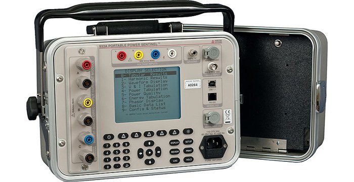
Model 933A Portable Power Sentinel™
Model 933A Portable Power Sentinel™
Arbiter's accurate and affordable portable power quality meter, with PMU compatible functions measuring synchrophasors, time, harmonics, flicker, K-factor, interruptions, phase and frequency.
Model 933A User Manual
Download PDF(4 MB) »
Model 933A Portable Power Sentinel™ Data Sheet
Download PDF(1 MB) »
Model 933A Portable Power Sentinel™ Data Sheet Español
Download PDF(310 kB) »
The perfect field analyzer for the power quality engineer, Model 933A Portable Power Sentinel™ is the most accurate and affordable portable power quality meter in the industry. The proprietary EnergyDSA™ Digital Signal Analysis algorithms allow the user to measure or record harmonics, flicker (per IEC 61000-4-15, PST and Instantaneous), K-factor and interruptions. The data logging capabilities allow the user to specify which data to log as well as when to log the data, continuously or when user specified thresholds are exceeded.
Time, Phase and Frequency Capabilities
Model 933A has the ability to also measure system time, phase, frequency and phasors. When synchronized using the IRIG-B IEEE-1344 unmodulated input or the GPS input, the Model 933A is capable of accurate revenue metering and synchrophasor analysis per the IEEE-1344. Pre-fault data is buffered for a half second allowing for accurate fault recording and event driven data analysis. The host processor and the DSP each have 128 MB of memory which provides ample space for data storage
Portability
Thanks to the high level of integration made possible with EnergyDSA™, this unit combines multiple capabilities into one compact, light weight instrument. Weighing less than 5.8 kg (12.8 lbs), the Portable Power Sentinel™ is a power quality monitor, a data and event logger, a system monitor, and a revenue meter designed to accompany you wherever you go and operate continuously for a full eight-hour shift. The unit comes pre-assembled with the adjustable tilt handle/bail assembly for easy transportability.
- Measures and records harmonics, flicker, K-factor, interruptions
- Support for synchrophasor measurements
- Optionally measures system time, phase, frequency and phasors
- Can be synchronized via IRIG-B IEEE-1344 unmodulated input or GPS input
- 320 pixel x 240 pixel graphic LCD display
- 30 key multifunction keypad
- RS-232 cable included
- RS-232 or USB 1.1 port
- External power supply or Battery operated (NiMH, with 8 hours typical run time)
Input/Output
Configuration
| 3 Ø: | 3-element, 2½-element, 2-element, selectable |
| 1 Ø: | 2-element, 1½-element, 1-element, selectable |
Voltage
| Range (3 Ø/1 Ø) | 1 Vrms to 650 Vrms, selectable (phase-to-phase for 2 and 2½-element; phase-to-neutral for 1 and 3-element) |
| Overrange | 1200 V peak, nominal |
Current
Model 933A-01 20 Amp direct input module:
| Range (3 Ø/1 Ø) | 0.05 Arms to 20 Arms, selectable, per element |
| Low Range | 1 mA to 1 Arms |
| Overrange | 40 A peak, nominal (maximum continuous input current: 20 Arms per element, all ranges |
VA, W, VAR
| Range | Any voltage, current and number of elements within the specified limits |
Compensation
| CT and PT | Both magnitude and phase compensation, CT with 12 point nonlinear interpolation |
| Transformer | Both iron and copper loss |
Frequency
| Range | 45 Hz to 65 Hz, for specified accuracy |
| Harmonics | to 3 kHz |
Inputs
| Voltage | Safety banana plugs |
| Current | 5-way binding posts (Model 933A-01) |
| Insulation | 400 volts, nominal, to neutral/chassis, surge voltage class III |
Power Quality
Harmonics Measurement
| Standard | 2nd to 50th (50 Hz or 60 Hz) per IEC 61000-4-7, 100 ms overlapping data window |
| Measurements | THD, K-factor, rms harmonic current and voltage, rms harmonic current and voltage with K-factor compensation (each harmonic magnitude is multiplied by the square of the harmonic number before summing), individual magnitude and phase |
| Logged Data | Selectable, may be regularly logged or registered. Event-logged also available when user-specified limits are exceeded |
Interruptions Logged Data
Selectable, may be regularly logged or registered. Event-logged also available when user-specified limits are exceeded.
Flicker
| Standard | Per IEC 61000-4-15, PST and Instantaneous |
| Logged Data | Selectable, may be regularly logged or registered. Event-logged also available when user-specified limits are exceeded. |
Limit Alarms
| Functions | Upper or lower limits may be set on most measured functions. Limits may also be set on maximum imbalance (ratio of Zero and Negative Sequence Components to Positive Sequence) |
| Output | Via system interface and display |
Accuracy/Specifications
Accuracy Note
Accuracy specifications include all sources of uncertainty. Except as noted, specifications apply for the full operating range, including temperature (- 10 °C to + 50 °C), line voltage, input range including specified overrange, power factor, input frequency, and drifts over a one-year calibration interval. Specifications assume synchronization to GPS and operation in 3-element mode or in a well-balanced system where imbalance does not degrade accuracy.
Watts
0.05 % of reading, for voltage 7 Vrms to 650 Vrms and current 10 mA to 20 Arms and PF > 0.2
Vrms
0.05 % of reading or ± 5 mV, whichever is greater. (For voltage 50 Vrms to 650 Vrms and current 50 mA to 20 Arms)
Arms
0.05 % of reading or ± 0.1 mA, whichever is greater. (For voltage 50 Vrms to 650 Vrms and current 50 mA to 20 Arms)
Phase Angle, Ø
Ø: 0.01 °, phase-to-phase or voltage-to-current (For voltage 50 Vrms to 650 Vrms and current 50 mA to 20 Arms)
0.2 % (current 10 mArms to 50 mArms)
Ø underrange: 0.05 ° of reading (current 10 mArms to 50 mArms)
VA, VAh
0.05 % of reading (For voltage 50 Vrms to 650 Vrms and current 50 mA to 20 Arms)
0.1 % (current 10 mArms to 50 mArms)
VAR, VARh
same as W, Wh except replace PF with (1 - PF2)0.5
Power Factor
0.0002 · sin (Ø) (For voltage 50 Vrms to 650 Vrms and current 50 mA to 20 Arms)
0.001 · sin (Ø) (current 10 mArms to 50 mArms)
Harmonics
0.1 % THD or 5 % of reading, whichever is greater
Frequency
< 1 ppm (0.0001 %) of reading, 50 Hz or 60 Hz nominal, plus timebase error
System
| Phase | 0.03 ° + [timebase error · 360 ° · frequency] (With GPS Option) |
| Time | 1 µs + timebase error (With GPS Option) |
Event Inputs
± 10 µs (typical)
Flash Memory Data Storage
Host Processor
| Capacity | 128 MB. See Operation Manual for record length and capacity calculations |
| Data | All functions measured and totalized by Model 933A; each record is stored with a time tag |
| Storage Rate | Selectable |
| Lifetime | 100,000 storage cycles minimum |
| Data Retention | Indefinite; no power or battery is required to retain data |
DSP Processor
| Capacity | 128 MB; about 1000 seconds or 17 minutes |
| Data | Primary waveform |
| Storage Rate | 10240 samples per second (approximately 170 samples per cycle). Fixed 30 cycles pre-fault data. Event data stored to Host Processor flash memory upon occurrence. User has same triggers as the Host Processor flash and can select the maximum fault duration, post fault recording time, and retrigger on/off. |
| Lifetime | 100,000 storage cycles minimum |
| Data Retention | Indefinite; no power or battery is required to retain data |
System Control and Monitoring
System Time, Phase and Frequency
| System Time | Unlimited accumulation with ± 1 µs resolution |
| Frequency | 6 digits, xx.xxxx Hz |
| System Phase | 0 ° to 360 ° with 0.01 ° resolution |
Phasors
| Standard | Per IEEE Standard 1344 or PSCSV |
| Rate | 20 measurements/second |
Interface
Operator
| Display | 320 pixel x 240 pixel graphic LCD display with CCFL Backlight |
| Keyboard | 30 keys: 5 soft function, 7 dedicated function, 5 cursor control, power on/off and 12 key numeric key pad |
Communications
| Serial | RS-232, RJ-11 modular connector |
| USB | Version 1.1, B-Type receptacle |
Protocols
| Proprietary | PowerSentinelCSV 933 (PSCSV933) |
Synchronization
IRIG TTL-Level Shift
TTL-Level Shift per IEEE-1344 as output from an Arbiter Systems Model 1084B
General/Remote
Optional Remote GPS receiver available. See Accessory AS0077600
| GPS Tracking | GPS-L1 (1575.42 MHz); 12 channel (tracks up to 12 satellites) |
| GPS Acquisition | 2 minutes typical |
| GPS Accuracy | UTC-USNO ± 1 µs (only need 1 satellite with correct position) |
| GPS Out of Lock | Via system interface and status display; optional, via contact closure |
Timebase Error
| GPS Locked | Less than 1 µs, when locked to at least one satellite with correct position |
| Unlocked | 10 ppm, typical, after being locked for 10 minutes minimum |
| IRIG-B | Less than 1 µs + accuracy of IRIG-B source |
General
Physical
| Size | 205 mm x 305 mm x 225 mm (8 in x 12 in x 8.8 in) |
| Weight | 5.8 kg (12.8 lbs), maximum |
Environmental
| Temperature | Operating: - 10 °C to + 50 °C |
| Humidity | Noncondensing |
Power Requirements
Internal Battery
| Type | NiMH |
| Operation | Eight hours typical |
| Charging | Four hours |
| Stand by Use | 5 VA typical |
External Power
| Range | 85 Vac to 264 Vac, 47 Hz to 63 Hz or 120 Vdc to 275 Vdc, 25 VA typical when charging battery, 5 VA typical standby use |
| Input | IEC connector with fuse; surge withstand per ANSI C37-90.1 and IEC801-4 standard |
| I/O | |
|---|---|
| 933Aopt01 1 | 20 Arms Direct Input Module with 5-way connectors |
| 933Aopt02 1 | 1.2 Arms or 2.4 Vrms CT Input Module with Banana Connectors |
| 933Aopt03 1 | 1.2 Arms or 2.4 Vrms CT Input Module with Audio Connectors |
1 Must select a minimum of one module at time of purchase.
| Included | |
|---|---|
| 812 | Safety Ground Lead |
| AP0007700 | Modular DB-9 to RJ-11 Adapter, Preconfigured |
| AS0093900 | Operation Manual (933A) |
| CA0023600 | RJ-11 Cable Four-Pin Crossed, 2 m (7 ft) |
| P01R-P10R | Country specific power cord with right angle female end |
| Available | |
| 09311A | 400 A 20:1 Precision CT, 0.1 % Accuracy |
| 811AT-8 | 3-Phase Univ. Test Plug Current Lead Set |
| 813AT-8 | 3-Phase Safety Voltage Lead Set |
| 815AT-8 | Model 815 Fused Safety Voltage Probe Lead Set |
| 816AT-8 | 3-Phase Spade-Lug Current Lead Set |
| 817AA-8 | 1-Phase Clamp-On CT Test Lead |
| 817AT-8 | 3-Phase Clamp-On CT Lead Set |
| 818AT-8 | 3-Phase Safety C-Hook Current Lead Set |
| 819xyz-8 | Modified Safety Clip Lead Set |
| 841A | Series Test Jack Isolator Paddle |
| 842A | Three - Series Test Jack Isolator Paddles with 60 cm Nylon Cord |
| 842B | Four - Series Test Jack Isolator Paddles with 60 cm Nylon Cord |
| AP0012300 1 | 100:1 Clamp-on CT, 150 A, 10 mV/A (1 V @ 100 A ac) |
| AP0012800 | 1000:1 Clamp-on CT, 200 A, 1 mA/A (100 mA @ 100 A ac) |
| AS0035901 | Adjustable Tilt Handle/Bail Assembly |
| AS0036000 | 400 A CT Bracket (each) |
| AS0077600 | Remote GPS Receiver with mounting bracket and 15 m (50 ft.) cable |
| AS0077700 | Programmable KYZ Contacts and Event Inputs |
| AS0079001 | Universal Test Plug Current Shunt, A Phase Red |
| AS0079002 | Universal Test Plug Current Shunt, B Phase Yellow |
| AS0079003 | Universal Test Plug Current Shunt, C Phase Blue |
| AS0079030 | Universal Test Plug Current Shunt, Set of Three |
| AS0097700 | 20 Arms Direct Input Module with 5-way connectors |
| AS0097800 | 1.2 Arms or 2.4 Vrms CT Input Module with Banana Connectors |
| AS0097900 | 1.2 Arms or 2.4 Vrms CT Input Module with Audio Connectors |
| CA0026106 | USB Data Cable, 6 ft |
| CA0027100 2 | CT Cable, Current Output, 6 ft |
| CA0027200 2 | CT Cable, Voltage Output, 6 ft |
| CA0029800 | Receiver Cable Extender 7.6 m (25 ft.) |
| CN0030500 | Adaptor Banana Shielded - Red |
| CN0030501 | Adaptor Banana Shielded - Black |
1 Requires Option 02 or Option 03
2 Required with Option 03
| Click to Download Latest Version of Software | |
|---|---|
| 933_PSCSV_17Jun2013_1132 | Configuration Utility |
| 933_PSCSV_SHA256_17Jun2013_1132 | 933A_PSCSV SHA256 checksum |
| 933_Uploader_05Feb2010_0050 | Required to upload firmware to Model 933. |
| 933_Uploader_SHA256_05Feb2010_0050 | 933_Uploader SHA256 checksum |
Software Version and Related Information
Read the release notes BEFORE downloading any software.
933_PSCSV
System Requirements:
- CPU: 486 or better.
- Operating system: Windows XP and newer. Click here for Arbiter software installation guidelines for Windows 7 and 10.
- Common Controls v4.71 or better.
| Version | Rev Level | Version Notes |
|---|---|---|
| 17Jun2013 | 1.132 |
|
| 27Apr2010 | 1.129 |
|
933_PSCSV_SHA256
| Version | Rev Level | Version Notes |
|---|---|---|
| 17Jun2013 | 1.132 |
933_Uploader
| Version | Rev Level | Version Notes |
|---|---|---|
| 05Feb2010 | 0.0.5.0 | Latest Version |
933_Uploader_SHA256
| Version | Rev Level | Version Notes |
|---|---|---|
| 05Feb2010 | 0.0.5.0 |
| Firmware Information (EPROM based firmware is not available for download) | |
|---|---|
| 933_Firmware_01Oct2012_117 | Downloadable. Requires 933uploader. |
| 933_Firmware_SHA256_01Oct2012_0117 | 933_Firmware SHA256 checksum |
Firmware Version and Related Information
How do I find my firmware revisions?
From the 933A front panel:
- Press the DISPLAY button.
- Press the 9 button.
- Press VERSION & S/N hot key
- The VERSION & SERIAL NUMBER display will show the versions, serial numbers, and calibration dates for the UNIT and the CURRENT MODULE
From PSCSV:
- Run PSCSV and connect to the 933A.
- Click on Connection.
- Click on Information. A window with the Firmware version and DSP version will pop up.
Downloadable firmware (933_Firmware)
| Version | Rev Level | Version Notes |
|---|---|---|
| 01Oct2012 | 1.17 |
|
| 24Jan2011 | 1.15 |
|
| 24Nov2010 | 1.14 |
|
| 22Sep2010 | 1.13 |
|
| 18Feb2010 | 1.12 |
|
| 31Aug2009 | 1.11 |
|
| 18Aug2009 | 1.10 |
|
| 28Jul2009 | 1.09 |
|
| 17Jun2009 | 1.08 |
|
| 12Jan2009 | 1.07 |
|
| 17Sep2007 | 1.06 |
|
| 03Aug2007 | 1.05 |
|
| 22Feb2007 | 1.04 |
|
| 20Dec2006 | 1.03 |
|
| 11Dec2006 | 1.01 |
|
933_Firmware_SHA256
| Version | Rev Level | Version Notes |
|---|---|---|
| 01Oct2012 | 01.17 |
Remote GPS Receiver for Model 933A
Download 933A_remote_gps_receiver.pdf (392 kB) »
Using SensorLink Litewires with the Model 933A
Download Using_SensorLink_Litewires_with_933A.pdf (1 MB) »