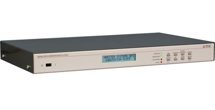
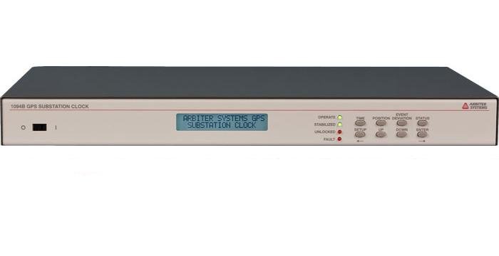
Model 1094B GPS Substation Clock (250 ns)
Model 1094B GPS Substation Clock (250 ns)
Includes the most commonly requested features and accuracy ratings for typical substation applications, all at a competitive price point.
Model 1094B User Manual
Download PDF(3 MB) »
Model 1094B Quick Setup Guide
Download PDF(179 kB) »
Model 1094B Data Sheet
Download PDF(2 MB) »
Model 1094B Data Sheet Español
Download PDF(486 kB) »
GNSS Antenna Data Sheet
Download PDF(4 MB) »
Combining world-class accuracy with value pricing, Model 1094B delivers as standard the most commonly requested features for substation applications in Arbiter's line of precision timing products.
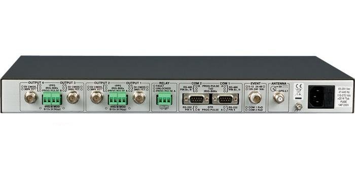
Standard features include a 12 channel GPS receiver with typical accuracy to < ± 100 ns, two serial communications ports, and four standard outputs supporting both BNC and 5 mm terminal strip connections, selectable to output IRIG-B, 1 PPS or programmable pulse A or B functions.
Able to output 5 Vdc, the unit can easily drive multiple loads in parallel, including synchrophasors. GPS Data Back Up battery capable of maintaining the real-time clock, almanac and ephemeris data in the case of power loss.
- Accuracy < ± 100 ns typical; < ± 250 ns worst case
- Four outputs configurable for BNC or 5mm terminal strip connectors
- One Form C (SPDT) fail-safe relay
- Two RS-232 and RS-422/485 ports available
- IEEE C37.118-2005 compliant for Synchrophasor use.
Receiver Characteristics
Timing Accuracy
| Accuracy Note | Specifications apply at the 1 PPS output, in the presence of Selective Availability (SA), as of date of publication. |
| Accuracy UTC/USNO | ± 250 ns peak; < ± 100 ns typical (SA off) |
Satellite Tracking
Twelve (12) channel, C/A code (1575.42 MHz). Receiver simultaneously tracks up to twelve satellites.
Acquisition
- 150 seconds typical, cold start
- 15 minutes, 90 % confidence, cold start
- 40 seconds, with almanac less than 1 month old
- 15 seconds, with ephemeris less than 4 hours old
I/O Configuration
Output Connectors
Four, each with BNC and 5 mm pluggable terminal strip in parallel.
Output Signals
Jumper selectable to high-drive 5 Vdc (250 mA at > 4 V) selectable to:
- IRIG-B00x level-shift,1 PPS orProgrammable Pulse A or B
- IRIG-B12x modulated
- 300 volt MOSFET output.
The MOSFET output is selectable to the same functions as the high drive 5 Vdc output. The MOSFET output is not electrically isolated from instrument common.
Programmable Pulse Output
Two programmable pulse outputs, PPA and PPB. PPA is available (by a jumper connection) on outputs 1, 2 and COM 1 pin 4 (RS-232) and pins 8 and 9 (RS-485). PPB is available (by a jumper connection) on outputs 3, 4 and COM 2 pin 4 (RS-232) and pins 8 and 9 (RS-485).
Six modes:
- Every 1 second to 60,000 seconds, starts top of the minute
- Hourly at a specified offset
- Daily at a specified time of day
- One shot at a specified time of year
- 1 PPS to 1000 PPS squarewave (PPB only)
- Aux IRIG Mode (PPB only)
Pulse duration is programmable from 0.01 seconds to 600 seconds, except in one-shot mode, where the output is Low prior to the specified time and High thereafter.
Relay Contacts
One, Form C (SPDT) fail-safe, 0.3A at 130 Vdc; jumper selectable to Fault, Unlocked, or Programmable Pulse A (PPA) functions. Fail-safe means the relay indicates "fault" or "unlocked" condition with power off.
Input Connectors
Event A Input:
One opto-isolated event capture input with 100 ns resolution, BNC connector jumper-configurable to 5 Vdc to 12 Vdc, 24 Vdc to 48 Vdc and 120 Vdc to 240 Vdc nominal input. Event input is also jumper-configurable to COM 1 and COM 2 RXD line.
Interface
Operator
| Display |
|
| Functions |
|
| Status LEDs |
|
| Keyboard | Eight keys |
| Setup |
|
System
| RS-232 | 1200 baud to 38,400 baud; 7 or 8 data bits; 1 or 2 stop bits; even/odd/no parity |
| RS-422/485 | Transmit only, to drive multiple devices. Two outputs. Uses extra pins on Com 1 and Com 2. |
| Broadcast modes |
|
| Connector | 2 Male 9-pin D-sub Com 1 and Com 2(TXD, RXD, AUX IN, AUX OUT) |
Power Requirements
Standard
| Voltage | (Option 07) 85 Vac to 264 Vac, 47 Hz to 440 Hz, 20 VA maximum or 110 Vdc to 370 Vdc, 15 W maximum |
| Inlet | (Option 07) IEC-320 with fuse and mating cordset. Specify option P01 - P10 Available cordset plug style and specifications are described in the Options and Accessories section. |
General
Physical
| Size | 1 RU rack mount or tabletop, 260 mm deep FMS, Rack mounts included. |
| Weight | 2 kg (4.5 lbs), net |
| Antenna | Cable Connection: F-type |
| Antenna Cable | Type: RG-6, 15 m (50 ft) provided |
| Antenna Mounting | 0.75 in pipe (1 in - 14 marine) thread |
Environmental
| Temperature | Operating: 0 °C to + 50 °C (- 20 °C to + 70 °C typical) Nonoperating: - 40 °C to + 85 °C |
| Humidity | Noncondensing |
| EMC | Radiated susceptibility: passes walkie-talkie test. Conducted emissions: power supply complies with FCC 20780, Class A and VDE 0871/6.78 Class A. Surge withstand capability (SWC), power inlet: designed to meet ANSI/IEEE C37.90-1 and IEC 801-4 |
Certificates and Approvals
CE mark/label and certificate
The available power options are listed below and are described in the Options and Accessories section, see our Product Catalog.Options and Accessories Options and Accessories section.
| Power | |
|---|---|
| 1094Bopt07 | IEC-320 Power Inlet 85 Vac to 264 Vac RMS, 110 Vdc to 370 Vdc |
| 1094Bopt08 | 10 Vdc to 60 Vdc Terminal Power Strip and Surge Withstand |
| 1094Bopt10 | 85 Vac to 250 Vac RMS, 110 Vdc to 350 Vdc Terminal Power Strip and Surge Withstand |
| Included | |
|---|---|
| AS0028200 | 19 Inch Rack Mount Kit |
| AS0099200 | Arbiter Universal GNSS Antenna |
| CA0021315 1 | 15 m (50 ft) RG-6 Antenna Cable, RoHS |
| P01 - P10 2 | Country specific power cord with straight female end |
| PD0052800 | Quick Setup Guide (1094) |
| Available | |
| AP0003400 3 | BNC (Male) Breakout to 100 mm Wires |
| AP0008900 4 | BNC (Female) Breakout to 100 mm Wires |
| AP0013400 | GNSS Antenna Cable Splitter, F-Type, 950-2150 MHz, One Port Pass DC |
| AP0014900 5 | BNC (Female) Breakout to Screw Terminal |
| AP0015000 6 | BNC (Male) Breakout to Screw Terminal |
| AS0033100 | Rack Slide Kit |
| AS0044600 | Antenna Mounting Kit |
| AS0044700 7 | 21 dB In-Line Pre-amplifier |
| AS0048900 | Antenna Grounding Block Kit, RoHS |
| AS0056600 | 24 Inch Rack Mount Kit |
| AS0083400 | Operation Manual (1094) |
| AS0094500 | GNSS Surge Arrester |
| CA0019806 | RS-232 Null Modem Cable, DB9F-DB9F, 2 m (6 ft) length |
| CA0021302 1 | 2 m (6 ft) RG-6 Antenna Cable, RoHS |
| CA0021306 1 | 6 m (20 ft) RG-6 Antenna Cable, RoHS |
| CA0021330 1 | 30 m (100 ft) RG-6 Antenna Cable, RoHS |
| CA0021338 1 | 38 m (125 ft) RG-6 Antenna Cable, RoHS |
| CA0021345 1 | 45 m (150 ft) RG-6 Antenna Cable, RoHS |
| CA0021350 1 | 50 m (164 ft) RG-6 Antenna Cable, RoHS |
| CA0021360 1 | 60 m (200 ft) RG-6 Antenna Cable, RoHS |
| CA0021375 1 | 75 m (250 ft) RG-6 Antenna Cable, RoHS |
| CA0026000 8 | Power Cord IEC-320 to Bare Leads |
| CN0027700 | Type F, Male, RG-6 Antenna Cable Crimp-on Connector, non-RoHS |
| CN0027800 | Type F, Male, RG-11 Antenna Cable Crimp-on Connector, non-RoHS |
| CN0050700 | Type F, Male, RG-6 Antenna Cable Compression Connector, RoHS |
| CN0050800 9 | Type F, Male, RG-6 Plenum Rated Antenna Cable Compression Connector, RoHS |
| CN0051300 | Type F, Male, RG-11 Antenna Cable Compression Connector, RoHS |
| TF0006000 | Type F, RG-11 Antenna Cable Crimp Tool |
| TF0006400 | Type F, RG-6 Antenna Cable Crimp Tool |
| TF0013200 | Antenna Cable Stripping Tool, RG-6 |
| TF0013300 | Antenna Cable Stripping Tool, RG-11 |
| TF0024000 | Type F, RG-6 Antenna Cable Compression Tool |
| TF0024100 | Type F, RG-11 Antenna Cable Compression Tool |
| WC0004900 1 | 300 m (1000 ft) Roll RG-11 Cable, RoHS |
| WC0005000 1 | 300 m (1000 ft) Roll RG-6 Cable, RoHS |
| WC0005200 10 | 300 m (1000 ft) Roll RG-6 Plenum Rated Cable, RoHS |
1 Stocked length. Custom lengths available from 0.3 m (1 ft) to 300 m (1000 ft). Contact factory.
2 Only applies if Power Option 07 is ordered
3 Converts female BNC-terminated coaxial cable to pair of wires.
4 Converts male BNC-terminated coaxial cable to pair of wires.
5 Converts pair of wires to female BNC.
6 Converts pair of wires to male BNC.
7 Used for cable lengths greater than: RG-6 75 m (250 ft) ; RG-11 100 m (328 ft). For the Models 120x: Used for RG-6 cable lengths greater than 100 m (328 ft)
8 Used with Option 07.
9 Indoor use only. Not weather resistant. Not UV radiation protected.
10 Stocked length. Custom lengths available from 0.3 m (1 ft) to 300 m (1000 ft). Contact factory. Indoor use only. Not weather resistant. Not UV radiation protected.
| Click to Download Latest Version of Software | |
|---|---|
| 1094_Utility_22Jan2019_1400 | View and modify configuration settings. |
| 1094_Utility_SHA256_22Jan2019_1400 | 1094_Utility SHA256 checksum |
| Tera Term_01Jan2010_23 | This is a very good HyperTerminal replacement. Able to capture data from Models 930A and 931A. Also able to program the GPS Satellite Controlled Clocks via serial commands. |
| Tera Term SHA256_01Jan2010_23 | Tera Term SHA256 checksum |
Software Version and Related Information
1094 GUI Utility Software (1094_Utility)
The software interface specifically written for the Model 1094B.
- Allows configuration of Model 1094B
- Supports viewing and modification of existing configuration on Model 1094B from your PC.
- Saves the existing configuration file from the 1094B to your PC.
- Compatible with Windows 7, 8, 10
| Version | Rev Level | Version Notes |
|---|---|---|
| 22Jan2019 | 1.4.0.0 |
|
| 20Sep2018 | 1.3.0.0 |
|
| 09Feb2016 | 1.2.0.0 |
Note: Please be sure to update to the 1094Utility.exe to v1.2 prior to installing the latest firmware on your Arbiter 1094 clock. This updated version of the utility fixes a communication problem when uploading the latest firmware. |
| 22Jan2014 | 1.0.0.0 | Completely rewritten to work better with newer Windows operating systems.
|
| 19Aug2009 | 0.9.4.0 |
|
1094_Utility_SHA256
| Version | Rev Level | Version Notes |
|---|---|---|
| 22Jan2019 | 1.4.0.0 |
Terminal Emulation Program (Tera Term)
Free software terminal emulator (communications program) for Microsoft Windows.
- Tera Term (Pro) is a free software terminal emulator (communication program) for MS-Windows.
- Supports VT100 emulation, telnet connection, serial port connection, etc.
- Compatible with Windows 98, Windows NT, Windows 2000, Windows XP, Vista, Windows 7
Tera Term SHA256
| Firmware Information (EPROM based firmware is not available for download) | |
|---|---|
| 1094_Firmware_25Feb2019 | Downloadable. Use the 1094 Utility to import file into unit. |
| 1094_Firmware_SHA256_25Feb2019 | 1094_Firmware SHA256 checksum |
Firmware Version and Related Information
Read the release notes BEFORE downloading any firmware
IMPORTANT: The firmware can only be updated if you have a firmware version of at least 2008. If your version is pre-2008, contact technical support for assistance. See below for instructions how to check your version number.
How do I find my firmware revision?
Using Serial Commands:
- Start a terminal program such as TeraTem (available for download on this page)
- Configure for 9600, 8, N, 1
- Press V
- Press E
- The terminal program should show the firmware revision date in the format dd mmm yyyy.
Using the 1094GUI utility program (1094utility_vxxxx.exe):
- The xxxx refers to the version number of the 1094BGUI Utility
- Connect the 1094B to the computer
- Run 1094GUI (1094utility_vxxxx.exe)
- Click the Version tab
- If the data is blank then click Unit > Read
Contact Technical Service if your current firmware is prior to 2008.
Downloadable Firmware (1094_Firmware)
| Version | Rev Level | Version Notes |
|---|---|---|
| 25Feb2019 | Updates are not security related.
Do NOT load older firmware to the new processor. Just don't try it. Doing so will quickly remove the ability of the 1094B to function properly. Posted to web site: 27 February 2019. |
|
| 07Jun2018 | Updates are not security related.
Do NOT load older firmware to the new processor. Just don't try it. Doing so will quickly remove the ability of the 1094B to function properly. Posted to web site: 20 September 2018. |
|
| 07Dec2017 | Updates are not security related.
Do NOT load older firmware to the new processor. Just don't try it. Doing so will quickly remove the ability of the 1094B to function properly. |
|
| 17Aug2017 | Updates are not security related.
|
|
| 22May2017 | Updates are not security related.
|
|
| 03Apr2017 | Updates are not security related.
|
|
| 10Oct2016 | Updates are not security related.
|
|
| 08Feb2016 |
|
|
| 05Nov2015 |
|
|
| 27Jul2015 |
|
|
| 04Jun2014 |
|
|
| 30Jul2013 |
|
|
| 05Dec2011 |
|
|
| 13Oct2011 |
|
|
| 06Sept2011 |
|
|
| 26Jul2011 |
|
|
| 14Oct2010 |
|
|
| 23Aug2010 |
|
|
| 05Jan2010 |
|
|
| 17Nov2009 |
|
|
| 21Oct2009 |
|
|
| 30Jun2009 |
|
|
| 08Jun2009 |
|
|
| 09Mar2009 |
|
|
| 15Jan2009 |
|
|
| 31Jul2008 |
|
|
| 16Jan2008 | Add in application firmware update capability. The 1094 can now have its firmware updated by using either of the rear serial ports (doesn't require the interface card). |
1094_Firmware_SHA256
| Version | Rev Level | Version Notes |
|---|---|---|
| 25Feb2019 |
GPS Substation Clock Requirements
Download gps_substation_clock_requirements.pdf (25 kB) »
IRIG-B Time Code Accuracy, IED and System Design Issues
Download irig_accuracy_and_connection_requirements.pdf (31 kB) »
NERC PRC-002 and PRC-018 Compliance Statement
Download pd0042900a_NERC_PRC-002_PRC-018_compliance_statement.pdf (70 kB) »
Time in the Power Industry: How and Why We Use It
Download TimeInThePowerIndustry.pdf (407 kB) »
Why GPS Clocks Are Not Free
Download why_gps_clocks_arent_free.pdf (12 kB) »
App Note 101: Distributing Timing Signals in a High-EMI Environment
Download application_note_101.pdf (90 kB) »
App Note 103: Large Format Displays with Arbiter products
Download application_note_103.pdf (16 kB) »
GPS Antenna Mounting Bracket
Download antenna_mnt_bracket_brief.pdf (462 kB) »
GPS Antenna Mounting Bracket Instructions
Download pd0024700_gps_antenna_mounting_bracket.pdf (580 kB) »
GNSS Antenna Preamplifier Installation Instructions
Download pd0025300_gnss_antenna_preamplifier.pdf (3 MB) »
IRIG Standard 200-16
Download irig-b_200-16.pdf (857 kB) »
IRIG-B Specifications
Download irig_b_spec_brief.pdf (488 kB) »
Chassis Dimensions
Download chassis.pdf (4 MB) »
GNSS Surge Protector Installation Instructions
Download pd0045800_surge_protector_installation_instructions.pdf (110 kB) »
Reducing Overshoot and Ripple in Arbiter Products with High Drive Outputs
Download pd0046200_reducing_high_drive_overshoot.pdf (277 kB) »
Timing Signals, IRIG-B and Pulses
Download pd0043200_timing_signals_overview.pdf (197 kB) »
Catalogo de Productos de Sincronizacion y Frecuencia
Download catalogo_de_productos_de_sincronizacion_y_frecuencia.pdf (312 kB) »
Press Release: Leap Second Anomaly December 2016
Download PD0054900_LeapSecondPressRelease.pdf (70 kB) »
Model 1094B CE Declaration
Download 1094B_CE_declaration.pdf (287 kB) »
Antenna Cable Assemblies RoHS2 Declaration of Conformity
Download Antenna_Cable_Assemblies_RoHS2_DoC.pdf (286 kB) »