Reliable Use of GPS Timing in the Power Industry
Bruce H. Roeder
International Marketing Manager, Arbiter Systems®, Inc.
The Global Positioning System (GPS) is a global navigation satellite system (GNSS) developed by the United States Department of Defense and managed by the United States Air Force 50th Space Wing. It is the only fully functional GNSS in the world.
It can be used freely by anyone, unless the system is technically restricted. These restrictions can be applied to specific regions by the U.S. Department of Defense. GPS can be used almost anywhere near the earth, and is often used by civilians for navigation purposes.
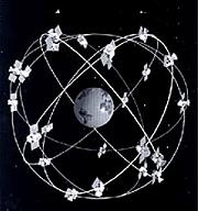
An unobstructed line of sight to four satellites is required for non-degraded performance. GPS horizontal position fixes are typically accurate to about 15 meters (50 ft). GPS uses a constellation of between 24 and 32 medium Earth orbit satellites that transmit precise radiowave signals, which allow GPS receivers to determine their current location, the time, and their velocity. Its official name is NAVSTAR GPS.
GPS (Global Positioning System) is the most widely used method of providing time synchronization in the world wide power industry. It is used as a reference for IEDs in substations and instrumentation measuring synchrophasors. It is also frequently used for network timing. The reliability of this critical reference is affected by many things:
- Proper Implementation of the Technology by Clock Manufacturers
- Potential Addition of Selective Availability to the GPS Signal
- Number of Satellites Received
- Antenna Location
- Number of Satellites Required for Timing
- Sources of Interference
- Proper Distribution of the Timing Signal
In addition to the above issues there is the upcoming (2010) loss of some of the GPS satellites due to the late deployment of the new group III GPS satellites.
This paper addresses each of these issues with recommendations to maintain reliable timing regardless of where your timing is required.
History of GPS
The first satellite navigation system, Transit, used by the United States Navy, was first successfully tested in 1960. It used a constellation of five satellites and could provide a navigational fix approximately once per hour. In 1967, the U.S. Navy developed the Timation satellite which proved the ability to place accurate clocks in space, a technology that GPS relies upon. In the 1970s, the ground-based Omega Navigation System, based on phase comparison of signal transmission from pairs of stations, became the first worldwide radio navigation system. Friedwardt Winterberg proposed a test of General Relativity using accurate atomic clocks placed in orbit in artificial satellites. To achieve accuracy requirements, GPS uses principles of general relativity to correct the satellites’ atomic clocks.
The design of GPS is based partly on similar ground-based radio navigation systems, such as LORAN and the Decca Navigator developed in the early 1940s, and used during World War II. Additional inspiration for the GPS came when the Soviet Union launched the first man-made satellite, Sputnik in 1957. A team of U.S. scientists led by Dr. Richard B. Kershner were monitoring Sputnik's radio transmissions. They discovered that, because of the Doppler Effect, the frequency of the signal being transmitted by Sputnik was higher as the satellite approached, and lower as it continued away from them. They realized that since they knew their exact location on the globe, they could pinpoint where the satellite was along its orbit by measuring the Doppler distortion (see Transit (satellite)).
After Korean Air Lines Flight 007 was shot down in 1983 after straying into the USSR's prohibited airspace, President Ronald Reagan issued a directive making GPS freely available for civilian use, once it was sufficiently developed, as a common good. The first satellite was launched in 1989 and the 24th and last satellite was launched in 1994.
Initially the highest quality signal was reserved for military use, and the signal available for civilian use intentionally degraded ("Selective Availability", SA). Selective Availability was ended in 2000, improving the precision of civilian GPS from about 100m to about 20m.
In 1998, U.S. Vice President Al Gore announced plans to upgrade GPS with two new civilian signals for enhanced user accuracy and reliability, particularly with respect to aviation safety and in 2000 the U.S. Congress authorized the effort, referring to it as GPS III.
On May 19, 2009, the U. S. Government Accountability Office issued a report warning that some GPS satellites could fail as soon as 2010.
Proper Implementation of the Technology by Clock Manufacturers
The GPS system was designed for navigation, and even though it is based on time to achieve positioning, it is more difficult to get accurate timing from the system than positioning. This is so because timing errors cancel out when solving for position, but they do not when solving for time. The manufacturer must take this into account when designing the phase lock loop to the 1PPS GPS signal and especially error detection and correction. Also compensation for circuit time delays, antenna time delays, and distribution delays. Frequently we see timing inconsistencies from the acquisition and loss of satellites which must be addressed by the clock manufacturer. I will discuss this more below in "NUMBER OF SATELLITES REQUIRED FOR TIMING".
Potential Addition of Selective Availability to the GPS Signal
GPS includes a (currently disabled) feature called Selective Availability (SA) that adds intentional, time varying errors of up to 100 meters (328 ft) to the publicly available navigation signals. This was intended to deny an enemy the use of civilian GPS receivers for precision weapon guidance.
SA errors are actually pseudorandom, generated by a cryptographic algorithm from a classified seed key available only to authorized users (the US military, its allies and a few other users, mostly government) with a special military GPS receiver. Mere possession of the receiver is insufficient; it still needs the tightly controlled daily key.
Before it was turned off on May 1, 2000, typical SA errors were 10 meters (32 ft) horizontally and 30 meters (98 ft) vertically. Since being turned off in 2000 the SA has been reinstated at least twice (Kuwait and Iraq wars). When reinstated GPS clocks which have been designed without provisions to correct for the added error range in their tuning algorithms typically fail until the SA is turned off again. Many GPS clocks were designed in response to the August 2003 outage on the East Coast which was after SA had been turned off. If you are concerned about SA contact the manufacturer and see what, if any, specifications they have in the presence of SA. Right now SA will not be implemented in the group III satellites.
Number of Satellites Received
Most receivers these days track twelve satellites simultaneously; however this is somewhat misleading due to the fact that they tend to discard all but the "best" four for calculating position. The number actually tracked is determined by position on the Earth (above and below 50 degrees north and south there are fewer visible), antenna location, and interference. All current GPS receivers are optimized for positioning, which causes another problem discussed in detail below.
Antenna Location
Antennas should be placed in a place with as much view of the sky as possible, but NOT on top of a mast (otherwise known as a lightning rod!). If possible keep it on the roof of the structure. It is wise to ground the antenna cable at the building entrance. Also use of a surge suppressor is recommended in areas subject to lightning. At Arbiter we keep our antennas within the building behind a skylight.
Number of Satellites Required for Timing
To provide time to the sub-microsecond level only one satellite is necessary once position has been determined. Having said that be aware that most clocks require four or five satellites for timing. WHY? Well, 99+ % of the GPS market is for positioning. Four satellites are required for positioning (generally five so one can be thrown out of the calculations), so when the number of received satellites drops below that crucial number the receivers either lose lock or, worse yet, send out erroneous time (often in the 10-300 millisecond range). The same effect can be seen when switching satellites produces a timing glitch. Above and below 50 degrees latitude these receivers will go out of lock twice a day or more depending on antenna exposure. This can be tested by using a restricted view of the sky (out a window from inside a building) pointing north in the northern hemisphere and south in the southern hemisphere, and monitoring the 1PPS output deviation. Also, be sure to insist the clock manufacturer specifies how many satellites are required to meet their accuracy specification. At Arbiter we specify timing accuracy "worst case" with a single satellite AND selective availability on.
So you have a very good view of the entire sky, and you aren't somewhere that gets cold in winter you should not typically have any clock problems, at least until some of the satellites are shut down (as early as 2010). This is due to the group III GPS satellites being three years behind and counting. Needless to say this will exacerbate any problems with clocks that need a full complement of satellites to give accurate time.
Sources of Interference
Since GPS signals at terrestrial receivers tend to be relatively weak, natural radio signals or scattering of the GPS signals can desensitize the receiver, making acquiring and tracking the satellite signals difficult or impossible.
Space weather degrades GPS operation in two ways, direct interference by solar radio burst noise in the same frequency band or by scattering of the GPS radio signal in ionospheric irregularities referred to as scintillation. Both forms of degradation follow the 11 year solar cycle and are a maximum at sunspot maximum although they can occur at anytime. Solar radio bursts are associated with solar flares and their impact can affect reception over the half of the Earth facing the sun. Scintillation occurs most frequently at tropical latitudes where it is a night time phenomenon. It occurs less frequently at high latitudes or mid-latitudes where magnetic storms can lead to scintillation. In addition to producing scintillation, magnetic storms can produce strong ionospheric gradients that degrade the accuracy of SBAS systems.
Man-made EMI (electromagnetic interference) can also disrupt, or jam, GPS signals. In one well documented case, the entire harbor of Moss Landing, California was unable to receive GPS signals due to unintentional jamming caused by malfunctioning TV antenna preamplifiers.
We have been building GPS clocks for twenty years now and have never seen a location with man produced interference (radio towers etc.) that could not be addressed by higher performance antennas which are
widely available on the market. We have also never seen a problem with solar flares, although low now they should peak again around 2013. Having said that there is no protection from a very high radiation such as EMP (electromagnetic pulse). In that case accurate time will be the least of our worries!
Proper Distribution of the Timing Signal
This is a subject greatly under-appreciated in the industry. What good is accurate time if you don't correctly distribute it?
IRIG Time Codes
The Inter-Range Instrumentation Group (IRIG) of the Range Commanders’ Council, a US military test range body, was faced several decades ago with a problem. Each test range had developed its own, unique time code. These time codes were recorded with test data on data tape recordings. The time codes were all incompatible, which made it difficult or impossible for the ranges to exchange data. Therefore, IRIG set about developing a common set of time codes. These have become known as the ‘IRIG codes.’
These time codes have become widely used in both military and civilian applications. Particularly, the IRIG code B (generally abbreviated IRIG-B) has become widely accepted for time distribution in substations. This time code repeats each second, and has a total of 100 bits per second. Some of these are framing (sync) bits, some are assigned for time, and some are available for control functions. The basic IRIG-B code has an ‘ambiguity’ of one year, since it does not contain year data. The IRIG codes can provide both time-of-day information, and an accurate on-time mark.
IRIG-B code may be used in either logic-level (unmodulated) format, or as an amplitude modulated signal with a 1 kHz carrier (below). The modulated IRIG signal is particularly suitable for transmission over voice-band channels, including data channels on an instrumentation tape recorder. Because of the difficulty of accurately measuring the zero crossings, modulated IRIG-B code is capable of an accuracy better than one millisecond (one period of 1 kHz), but not usually better than ten microseconds. This level of accuracy is acceptable for some but not all substation applications. Modulated IRIG inputs to IEDs are generally transformer-isolated and provided with an automatic gain-control stage, so as to accept input signals with a wide range of amplitudes. A typical input level range is 0.1 Vpp to 10 Vpp.
The unmodulated IRIG B code can deliver accuracy limited only by the slew rate of the digital signal, much better than one microsecond and, with care, in the range of a few nanoseconds. Unmodulated IRIG-B is normally distributed at a level of 5 volts (compatible with TTL or CMOS inputs). While some IEDs couple the IRIG-B signal directly to a logic gate, best practice has for some time used an optically-isolated input to break ground loops. Well designed substation clocks can generally drive numerous inputs with either modulated or unmodulated IRIG-B signals, so a single clock can synchronize all the IEDs in a substation. The current version of the IRIG standard is IRIG Standard 200-04.
IEEE-1344 Extension to IRIG-B Time Code
The IRIG codes were originally developed for test-range use, and a one-year ambiguity was acceptable. Being a military code, times were always recorded in UTC (Coordinated Universal Time, military Zulu Time), so local offsets and summer time issues were also not a concern. Leapseconds, which happen once or twice a year or less, also were not a concern of the IRIG group. And the range officer would be required to guarantee that all recorders were synchronized properly before beginning a test.
Real-time operation, 24 hours per day, 365 days per year, year after year, imposes some additional requirements. The issues identified in the previous paragraph become real concerns. As part of the original Synchrophasor standard, IEEE Standard 1344-1995, an extension for the IRIG-B code was developed using the ‘control bits’ field to provide an additional 2 digits of year (subsequently adopted also by the IRIG standard), as well as local offset, time quality, and bits for leap second and summer time changeovers. Some IEDs support this extension, but many do not. You may find an occasional IED that requires the IEEE-1344 extension for proper operation. This may not be well documented in the product literature.
The IEEE-1344 extension also created a new ‘modified Manchester’ encoding scheme, which is a digital signal having zero average value, and suitable for transmission over an optical fiber. It encodes the same 100 bit/second data stream onto a 1 kpps square-wave carrier. This modulation method has also been accepted as part of the IRIG standard.
Signal levels and connection methods for the IRIG-B code, with or without the IEEE-1344 extensions, are identical. The only difference is the use of the control bits to provide the extra information required in continuous, real-time monitoring applications. This is a firmware feature, and does not affect the hardware interface. IEEE Standard 1344 has been supplanted by IEEE Standard C37.118, which also includes this information. This standard may be purchased from the IEEE in New Jersey, USA.
Additional information can be found in Arbiter Systems Application Note 101 - Distributing Timing Signals in a High-EMI Environment.
Network Time Synchronization
With the proliferation of IEDs in a modern substation, it is a natural question to ask: can we use the same connections to provide both data and synchronization? Within some limits, the answer is yes.
NTP and SNTP
NTP (Network Time Protocol) is a software method to transfer time between computers using a data network, such as the Internet. NTP is defined in an Internet Request for Comment document, RFC-1305. NTP generally provides moderate accuracy, from a few milliseconds up to a few hundred milliseconds depending on the nature of the connection between the NTP client and the server, and the performance of the computers’ operating systems. NTP includes methods to estimate the round-trip path delay between the server and client, and to ignore ‘outliers,’ or
path delay estimates which vary significantly from the typical value. However, even in the best case of a local network (e.g. Ethernet), typical performance is limited by the operating system stack latency, and is often no better than one millisecond in a wide area network the error is substantially worse (as much as 50 milliseconds).
SNTP is a version of NTP that does not include the sophisticated clock-discipline algorithms included in NTP. SNTP may be used at the ‘roots’ or ‘leaves’ of a network: points where time is either first sent to the network (from an accurate source such as GPS), or received by a client (such as an IED). Since this topology is valid for many simple substation networks, SNTP can be used in both servers (GPS clocks) and clients (IEDs) in a substation, with no need for NTP.
For best accuracy, the logical connection between the server and client should be as short as possible. With optimum design of both server and client, and optimum configuration of the network, accuracy of a few microseconds is possible. Arbiter is now working toward making this level of performance practical in the substation environment, but it is still some years away.
So either "copper" or network timing is possible using proper design of the distribution network or the data network. However for the accuracy required for certain applications, i.e. <1 microsecond (synchrophasors, end to end testing) IRIG-B will continue to be the preferred method for some time.
Conclusion
GPS timing will continue to be the most reliable and cost effective timing method for the power industry for the foreseeable future. However care must be taken when choosing clocks and when implementing distribution to the IED. The entire system must be robust and reliable at every step, or it will fail, most likely at the most crucial time. Hopefully by making the sub-station engineering group aware of these issues they can be taken into account when commissioning and maintaining their sub-stations.
« Back to Advancing the Technology Index